
Achieving high capacitance means going big. But how do you do that while still maximizing board space? At Knowles Precision Devices, we’ve developed a new method for building customizable large capacitor assemblies that capitalize on the vertical space above the circuit board. While stacked capacitor assemblies have been around for many years, these parts do not have very good bump and vibration withstand due to the thin leads used in their construction. These new assemblies from Knowles Precision Devices offer a ruggedized construction capable of withstanding high levels of shock and vibration. This offers a unique combination of capability, durability, high capacitance, and very high voltage in a smaller area, making these capacitors ideal for automotive, military, and aerospace applications.
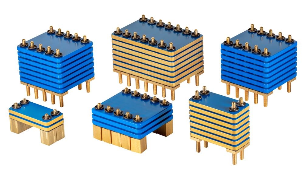
Our large capacitor assemblies are highly customizable both in height and shape and are built with reliability in mind. For these assemblies, we use large diameter pins that can handle high ripple currents and contact to the internal electrodes through a 360º connection, reducing resistive and inductive losses. The pins are mechanically decoupled from ceramic elements, allowing the assembly to withstand severe mechanical shock, vibration, and temperature variations. We also use a low-loss, ultra-stable C0G dielectric and have a high capacitance range of 10nF to 3.9µF and a voltage range from 500Vdc to 5000Vdc. These capacitor assemblies have also been through a variety of qualification tests as shown in Table 1 to demonstrate their capability.
| Stress | Reference | Additional Requirements |
| Pre- and Post-Stress Electrical Test | User Spec. | Test is performed at 25° ±5°C except as specified in the applicable stress reference and the additional requirements in this table. |
| High-Temperature Exposure (Storage) | MIL-STD-202 Method 108 | Unpowered. 1,000 hours. Measurement 24 ±4 hours after test conclusion. The maximum rated temperature should be employed for the dielectric used in the device. |
| Temperature Cycling | JESD22 Method JA-104 | 1,000 Cycles (-55°C to +125°C). Measurement at 24±4 hours after test conclusion. 30 min. maximum dwell time at each temperature extreme. 1 min. maximum transition time. |
| Destructive Physical Analysis | EIA-469 | Only applies to SMD Ceramics. Electrical test not required. |
| Biased Humidity | MIL-STD-202 Method 103 1 | 1,000 hours +85°C/85% RH. 1.3 to 1.5 volts |
| Operational Life | MIL-STD-202 Method 108 | Condition D Steady State TA= +125°C. Full rated for ceramic caps. Measurement at 24±4 hours after test conclusion. The maximum rated temperature and voltage rating for the dielectric employed in the device shall be used. |
| External Visual | MIL-STD-883 Method 2009 | Inspect device construction, marking and workmanship. Electrical test not required. |
| Physical Dimension | JESD22 Method JB-100 | Verify physical dimensions to the applicable device specification. |
| Mechanical Shock | MIL-STD-202 Method 213 | Figure 1 of Method 213: Condition C (150g) for qualification. Tested at up to 500g with no failures. |
| Vibration | MIL-STD-202 Method 204 | 5g for 20 min., 12 cycles each of 3 orientations. Note: Parts mounted within 2" from any secure point. Test from 10-2000 Hz. |
| ESD | AEC-Q200-002 |
Table 1. An overview of the stress tests and requirements we test to for our large capacitor assemblies.
Additionally, by using the vertical space above the board, we can replace multi-chip assemblies where large arrays of multilayer ceramic capacitors are placed in parallel on a circuit board. While this approach has been used before, traditional stacked caps are generally susceptible to mechanical shock and vibration. Therefore, there is nothing else on the market that can offer the same high bump and vibration loadings as our new large capacitor assembly. Figure 1 shows an example of a typical layout we can create.
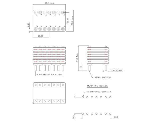 Figure 1. An example of a typical large capacitor assembly layout that corresponds to a 500V 3.9µF rated ultra-stable C0G/NP0 component.
This custom approach to large capacitor assembly enables us to better accommodate the specific needs of our customers when they have a project that requires high capacitance and proven durability in a tight space, such as electric vehicle and resonant wireless charging systems.
Talk to us today about creating a customized solution for your automotive, aerospace, or military applications, or any project requiring high capacitance and proven durability in a tight space.