Welcome to the Capacitor Fundamentals Series, where we teach you about the ins and outs of chips capacitors – their nature and properties, dielectric behavior, product classifications, test and quality standards, and common use cases – in order to help you make informed decisions about the right capacitors for your specific applications. Part 1 discusses the key principles of capacitance and how a basic capacitor works.
What is Capacitance?
Capacitance is the ability of a system (such as a component or circuit) to collect and hold energy in the form of electric charge. Capacitance value (C) is the ratio of the electric charge stored (Q) to the voltage applied (V), or C = Q/V. The charging current (I) is therefore expressed as I = dQ/dt = CdV/dt.
The value of capacitance is defined as one farad when the voltage across the capacitor is one volt, and a charging current of one ampere flows for one second.
C = Q/V = Coulomb/Volt = farad
Because the farad is a very large unit of measurement and is not encountered in practical applications, fractions of the farad are commonly used, such as:
· 1 picofarad (pF) = 10-12farad
· 1 nanofarad (nF) = 10-9farad
· 1 microfarad (μF) = 10-6 farad
What is a Capacitor?![Image[1]](https://blog.knowlescapacitors.com/hs-fs/hubfs/Images/2019/Image%5B1%5D.png?width=300&name=Image%5B1%5D.png)
A capacitor is a passive electronic component that is capable of storing electric charge in an electric field. Unlike a battery which stores energy and then gradually releases it, capacitors can be discharged in an instant. A basic unit consists of two conductors, or electrodes, separated from one another by an insulator, or dielectric.
Electrode Basics
In order to easily collect electric charge, the electrode must be a good conductor of electricity. Materials widely used in capacitor manufacturing include aluminum, copper, nickel, palladium, platinum, silver, and tantalum.
Depending on the manufacturing process used, the electrode may need to be unreactive with a high melting point. For example, the oxidizing atmosphere-fired ceramic capacitors manufactured at Knowles Precision Devices use a ceramic dielectric material with a sintering temperature of approximately 1100 °C. In order to stop the electrode from melting during firing, a combination of silver and palladium is used. This method of manufacture is referred to as the Precious Metal Electrode (PME) system.
Dielectric Basics
In order to store greater amounts of electric charge, the dielectric must be a good insulator, the properties of which largely determine the electrical behavior of the device. Dielectrics are characterized by their ability to store electrical charge and their intrinsic responses to an electric field, namely capacitance change, loss characteristics, insulation resistance, dielectric strength, as well as the aging rate and the temperature dependence of these properties.
The dielectric constant, or relative permittivity εr, refers to a material’s ability to store electrical energy in an electric field. It is the dominant characteristic that determines the capacitance value attainable at a given size and voltage. In other words, the higher the dielectric constant, the greater the capacitance for a particular capacitor design. Dielectric materials commonly used in capacitor manufacture include ceramics, porcelain, metal oxides, mica, and plastic film.
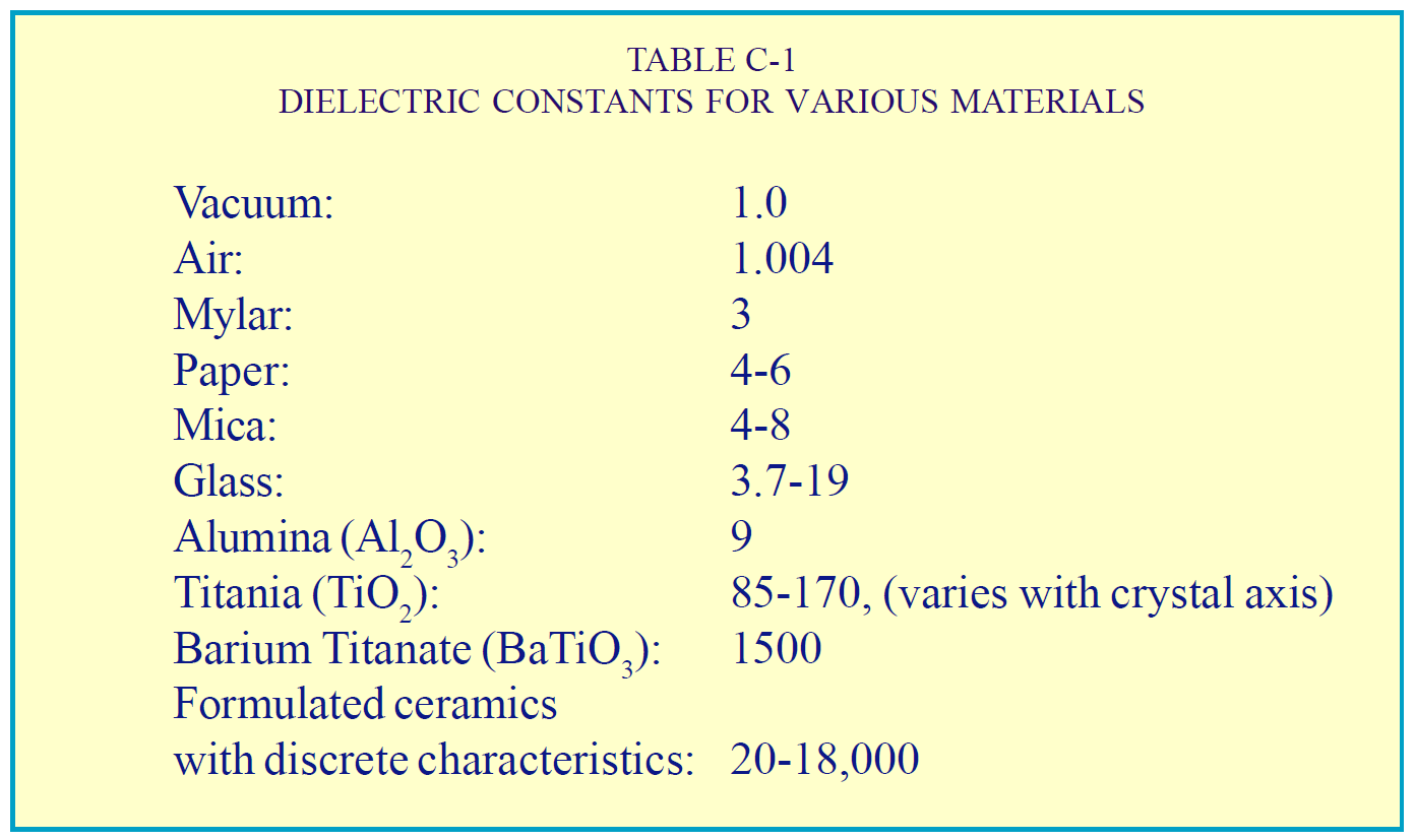
For example, ceramic capacitors can be categorized into two main types based on if they’re using C0G/NP0 dielectric (which have εrvalues between 20 and 100) or X7R dielectric (which have εrvalues of between 2000 and 3000).
Capacitor Construction
The most basic type of capacitor is a single layer that consists of a layer of dielectric material sandwiched between a positive and a negative electrode. A multilayer ceramic capacitor (MLCC) takes this concept and multiplies the number of layers to increase the available capacitance. Layers of ceramic are built up using a screen-printing process and are interleaved with electrodes of alternating polarity. The like polarity electrodes are then joined together using a termination material. The termination can then be attached to wires or legs to form a radial leaded MLCC or electroplated to form a surface mount MLCC.
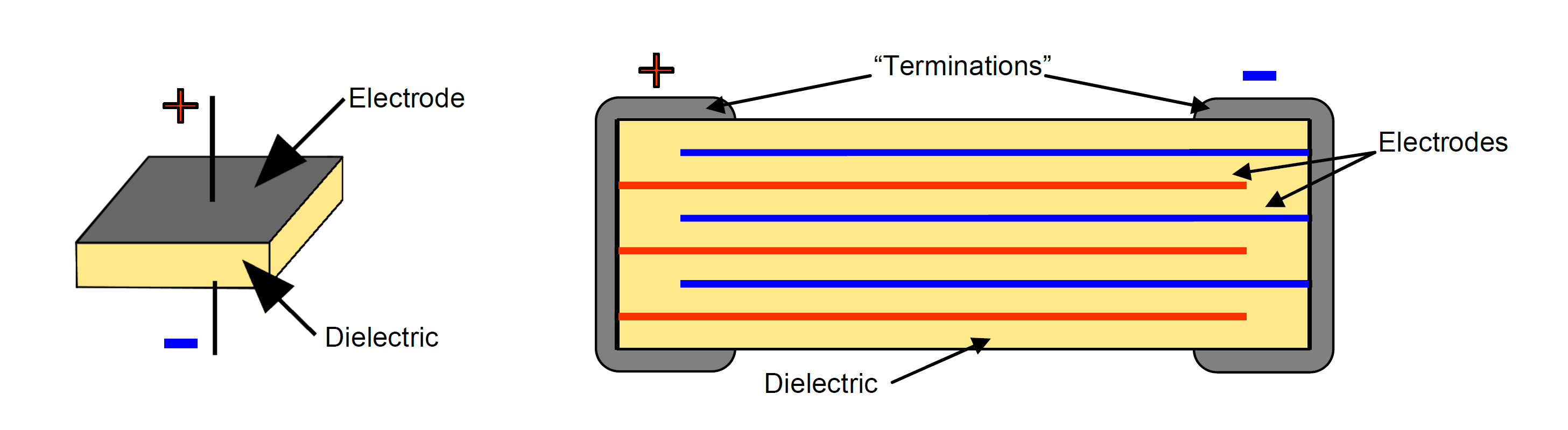
Single layer capacitor (left) versus multilayer capacitor (right)
Hopefully, Part 1 gave you a better understanding of capacitance and the components that make up a capacitor. In Part 2, we’ll be covering the most common use cases for capacitors. Also, check out our Knowles Precision Devices Capacitors to view our complete product offering.
To learn more about capacitors, download our ebook, A Guide to Selecting the Right Capacitor for Your Specific Application.