Welcome to the Capacitor Fundamentals Series, where we teach you about the ins and outs of chips capacitors – their properties, product classifications, test standards, and use cases – in order to help you make informed decisions about the right capacitors for your specific applications. After describing high reliability testing in our previous article, let’s discuss visual standards for chip capacitors.
External Visual Standards
Multilayer ceramic capacitors (MLCCs) must possess fine workmanship and physical integrity, so visual inspection of the product is performed at 20X magnification to check for defects in the capacitor body and end metallization. Visual standards are detailed in MIL-C-123B, Appendix C, and manufacturers typically inspect only sample quantities in accordance with MIL STD 105, Level II, 0.65. Acceptance or rejection of standard production lots is based on various defective criteria, as listed in Table 1 and depicted in Figure 1.
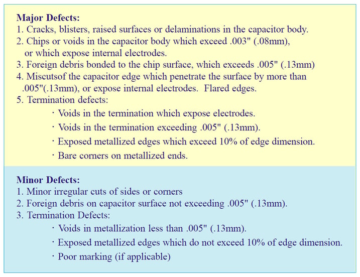
Table 1. Typical criteria for visual defects
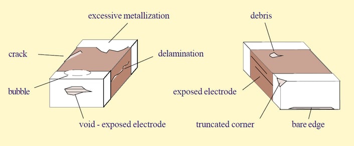
Figure 1. Visual defects
Internal Microstructure Standards
In addition to the external visual characteristics, quality standards for internal microstructure of the chip capacitor are also applicable, as viewed on polished cross sections of capacitor samples. Units are sectioned along the long and short dimension of the capacitor to provide two edge views of the internal electrodes and terminals.
Although any degree of internal defect is considered undesirable, the fact remains that these types of defects can occur occasionally in different degrees of severity. Typically, delaminations, internal voids, cracks, and other irregularities (see in Figure 2) are classified based on their severity and are considered to constitute defects if they exceed the criteria based on EIA 469.
Delaminations
A delamination is a separation of the structural layers of the capacitor, in the form of a planar cavity, between the electrode and ceramic or within the dielectric itself. Any delamination which can be considered to be detrimental to the electrical and mechanical integrity of the capacitor is classified as a defect, and generally involves the following:
- Any delamination in the active (electrode overlap) area, longer than 20% of the electrode length, or exceeding .010" (.254 mm), whichever is greater
- Any delamination greater than .005" (.127 mm), located within the electrode overlap area, and associated with displacement of adjacent electrodes and reduction of these dielectric layers by more than 50% of their thickness
- A delamination which exceeds 50% of the margin between the termination and electrodes of opposite polarity
- Two or more delaminations exceeding .010" which overlap each other in the active electrode area, in adjacent layers
Voids
Any void which can be considered detrimental to the electrical and physical integrity of the capacitor is classified as a defect, and generally involves the following:
- Any void between electrodes of opposite polarity, which reduces the dielectric thickness by more than 50%
- Any void in the cover plate of the capacitor which reduces the cover thickness to less than .003" (.076 mm), or less than the active dielectric thickness
- A void or bubble in the termination, not contacting the dielectric surface, which exceeds 30% of the chip end dimension
- A void or bubble in the termination, contacting the dielectric, which exceeds .020" (.508 mm)
Cracks
Any crack which can be considered detrimental to the electrical and physical integrity of the capacitor is classified as a defect, and generally involves the following:
- Any crack connecting any two electrodes
- Any crack connecting an electrode to any exterior surface of the chip, or to a termination
- Cracks extending from the termination metal band into the interior of the chip (also known as termination stress cracks)
Non-Uniformities
Irregularities in the construction of the chip capacitor do not necessarily affect the mechanical or electrical integrity of the device, but may be of concern in high reliability applications. The following is a compilation of structural irregularities according to the EIA 469:
- A side or end margin of dimension less than .003" (.076 mm) between 90% or more of the electrodes and the exterior dielectric surface
- Ceramic cover plate thickness which is less than the dielectric thickness between adjacent electrodes
- Variations in the active dielectric layers which result in areas with less than 50% of the nominal dielectric thickness
- Thick electrode depositions, exceeding 2.5 times the average electrode thickness, and extending over 50% of the electrode length
- Thick electrode deposition, extending over .005" (.127 mm), which also reduces the adjacent dielectric layer thickness by more than 30%
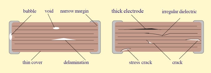
Figure 2. Microstructure defects
Sample Preparation Defects
A variety of imperfections observed on sectioned specimens can arise due to the method of sample preparation and must be identified (so as to preclude erroneous interpretation of results). Subtle observations and precautions can be followed to positively segregate preparation problems from actual defects. First, it is essential that the specimen be observed, prior to mounting in a section, to determine if any obvious mechanical flaws are present. Usually this is accompanied by inspection of basic electrical properties. Secondly, units must be rigidly encapsulated with non-shrinking (and hence stress-free) resin, followed by grinding and polishing with fine grit abrasives under controlled pressure to avoid cracking. Sections must be polished to remove all vestiges of the rough cuts used to reduce the specimen and then cleaned thoroughly before observation. This procedure will minimize the occurrence of most sectioning-induced defects (depicted in Figure 3).
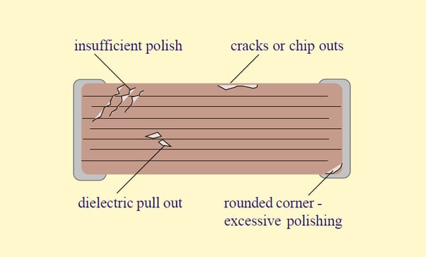
Figure 3. Sample preparation defects
The following criteria are used to attribute defects to sectioning methods:
- Void defects form linear patterns,e. they are induced by grit pulling material out of the ceramic during grinding, hence more polishing is required. Note that voids forming a line parallel to the layered structure of the device, a so-called “knit line,” may not fall into this category.
- Large voids are present, with virtually no distortion of the electrode pattern or of adjacent dielectric layers. The correctness of the structure around these voids is indicative as to their absence in the original unsectioned unit; thermal processing would otherwise result in collapse of the electrode and/ or distortion of layers around these voids. Such defects are caused by excessive pullout during grinding, particularly in the area between electrode layers, where there is minimal dielectric layer to layer bonding.
- Units exhibit cover sheet cracks and/or separation of the ceramic cover sheet from the electrode array, yet these were not evident on usual examination of the device prior to sectioning. These defects arise due to insufficient support in the encapsulant and/or excessive grinding methods. Such cracks may also appear parallel to the end terminations, as the termination to ceramic interface is mechanically weaker. Measurements of capacitance, dissipation factor (DF), insulation resistance, and termination pull strength can be used to confirm the absence of this defect in unsectioned product.
- Excessive polishing will round corners and edges of the section, resulting in depth of field distortions on observation, as well as difficulty with illumination. “Defects” which appear under these conditions may be nonexistent and should be disregarded.
Evaluation of visual and microstructure quality of chip capacitors is very subjective, and difficulties arise in correlating opinions between observers, especially when considering the minor category of defects described above. In addition, dissimilar images can occur when viewing product under differing light sources on a microscope. (Fluorescent lighting has been found to be superior over incandescent light in highlighting defects.) The acceptance or rejection of capacitors with any visual or microstructure defects is usually specified or determined by the chip user, based on the application of the product. High reliability or high voltage units must meet the most stringent standards.
Hopefully, Part 12 gave you a better understanding of visual test standards and how their results may affect your specific application. In Part 13, we’ll be diving into chip user guidelines. Also, check out our Knowles Precision Devices Capacitors to view our complete product offering.
To learn more about capacitors, download our ebook, A Guide to Selecting the Right Capacitor for Your Specific Application.


