When designing a ceramic capacitor, the type of dielectric used will influence the characteristics of the capacitor and define its electrical behavior. At a high level, there are two types of dielectrics made with ceramics – paraelectric and ferroelectric. Dielectrics containing paraelectric (or non-ferroelectric) ceramics are known as Class I dielectrics. These dielectrics show a linear relationship of polarization to voltage and are formulated to have a linear temperature coefficient. Capacitors using a Class I dielectric have high stability across various temperatures, but have low permittivity, which means the capacitor will offer low capacitance.
Dielectrics that contain ferroelectric ceramics are known as Class II dielectrics. These dielectrics provide a much higher permittivity, but the capacitance value is much less consistent over the temperature range. Class II dielectrics offer much higher dielectric constants than Class I dielectrics, but have less stable properties with regards to temperature, voltage, frequency, and time.
For both Class I and Class II dielectrics, the various combinations of temperature coefficients and operating temperatures result in different electrical characteristics for the dielectrics used in ceramic capacitors. Dielectrics are grouped into "application classes" based on these characteristics, and these application classes are defined by two separate sets of standards. One standard is from the International Electrotechnical Commission (IEC) and the other is from the Electronic Industries Alliance (EIA), an alliance that was disbanded in 2011 but has standards that still prevail and have since become part of the Electronic Components Industry Association (ECIA). Let’s dive into the classification systems used by each of these standards to help easily identify the temperature coefficients and operating temperatures for both dielectric classes.
Class I Dielectrics
For Class I dielectrics, the EIA RS-198 standard code defines a letter-number-letter code to describe the temperature coefficient of Class I dielectrics as follows:
- The first letter represents the significant figure of the change in capacitance over temperature in ppm/K
- The second number represents the multiplier of the temperature coefficient
- The third letter represents the maximum tolerance in ppm/K
These code combinations are shown in Table 1.

Table 1. Class I ceramic capacitor codes for temperature coefficients α referring to EIA-RS-198.
For example, a popular Class I dielectric used is C0G. This means this dielectric has a 0 +/- 30 ppm/K, or an allowable capacitance change of ±30 ppm/°C over the -55°C to 125°C operational temperature range. As a result, C0G dielectrics generally have K values between 20 and 100 and are used to make stable, lower capacitance parts in the picofarad (pF) to nanofarad (nF) region.
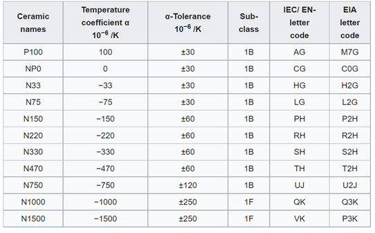
For the IEC/EN 60384-8/21 standard, the temperature coefficient and tolerance are replaced with the two letters of the EIA code used. For example, the corresponding IEC/EN code for C0G is CG. Ceramic names can also be broken down under both IEC/EN 60384-8/21 and EIA codes. Table 2 shows the different ceramic names with the temperature coefficient located within the name.

Table 2. Class I ceramic capacitor names, temperature, coefficients α, α tolerances, and letter codes for α referring to IEC/EN 60384-8/21 and EIA-RS-198.
Additionally, military specifications such as MIL-PRF-55681 and MIL-PRF-123 uses a separate format containing two letters. The rated temperature and voltage-temperature limits are identified by a two-digit symbol. The first letter "B" indicates the rated temperature of -55°C to +125°C and the second letter indicates the voltage-temperature limits as shown in Table 3. For example, BP calls out for a rated temperature of -55°C to +125°C and a voltage-temperature limit of 0 ± 30 ppm/°C.

Table 3. MIL-PRF-55681G with amendment 1 voltage temperature limits for Class I dielectrics.
Class II Dielectrics
Class II dielectrics are broken down differently than Class I dielectrics, but also labeled for the EIA ES-198 standard using a letter-number-letter system according to the change in capacitance over the temperature range in the following manner:
- The first letter gives the minimum operating temperature
- The second number gives the maximum operating temperature
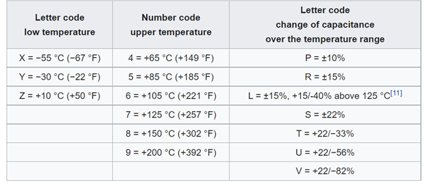
- The final letter gives capacitance change over the temperature range as shown in Table 4

Table 4. The Class II ceramic capacitors’ code system for EIA RS-198 for some temperature ranges and inherent change of capacitance.
Commonly used Class II dielectrics include X7R and X5R, which both call out a ±15 percent change of capacitance over temperature, but with different maximum temperatures.
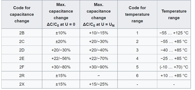
Like the codes used for the IEC/EN standard for Class I dielectrics, the IEC/EN standard uses a two-digit code as shown in Table 5.

Table 5. The code system for IEC/EN 60384-9/22 for some temperature ranges and inherent change of capacitance.
It is possible to translate the EIA code into the IEC/EN code, although some parts may not be complete translations. For example, EIA code X7R correlates to IEC/EN code 2X1, which call out for ±15 percent, operating temperature of −55°C to +125 °C.
Without an understanding of the dielectric coding systems in use today, dielectric selection can seem extremely complex and cryptic. But, by having this general understanding of the codes used to classify dielectrics, it is much easier to choose the best dielectric for your application.
To learn more about capacitors and dielectrics in general, download our Capacitor Fundamentals eBook.

