

When constructing multilayer ceramic capacitors (MLCCs), there are two classes of dielectrics electrical engineers typically select from depending on the application – Class 1, which consists of non-ferroelectric materials such as C0G/NP0, and Class 2, which are ferroelectric materials such as X5R and X7R. One key difference between these materials comes in the form of capacitance stability as voltage and temperature increase. With Class 1 dielectrics, capacitance will remain stable when DC voltage is applied and operational temperature increases. On the other hand, Class 2 dielectrics, which have a higher dielectric constant (K), are less stable with regards to temperature, voltage, frequency, and time.

While a variety of modifications can be made to increase capacitance, including changing the surface area of the electrode layers, the number of layers, the K, or the distance between the two electrodes, capacitance will still eventually dramatically decrease for Class 2 dielectrics when DC voltage is applied. This is because of a phenomenon called DC bias that causes Class 2 ferroelectric formulations to eventually experience a decrease in dielectric constant as DC voltage is applied.
For higher K materials, the impact of DC bias can be more severe as the capacitor can potentially lose up to 90 percent or more of its capacitance as shown in Figure 1.
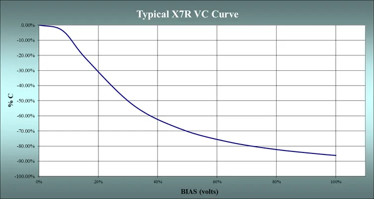
Figure 1. This is a typical voltage change curve for an X7R part.
The dielectric strength of a material, which is the voltage that a material of a given thickness will resist, can also change how DC bias impacts the capacitor. It is important to note that dielectric strength is usually given in volts per mil in the USA (where 1 mil equals 0.001 in), or volts per micron elsewhere. The thickness of the individual dielectric layers determines the volts/mil or volts/micron loading of the device during operation. Therefore, capacitors of identical capacitance value and voltage rating may behave quite differently depending on the internal construction of the capacitors.
When considering dielectric strength, it is also important to note that when a voltage is applied that is greater than the dielectric strength of the material, a spark will pass through the material and cause potential ignition or a small-scale explosion.
A Real-World Example of How DC Bias Occurs
If you couple the change in capacitance due to applied voltage with changes in temperature, capacitance loss will be even greater at certain applied temperatures and DC voltages. Let’s consider an MLCC constructed with X7R that has a capacitance of 0.1 μF and is rated for 200 VDC as an example. This MLCC is constructed with 35 layers that are 1.8 mils (0.0018 inches or 45.72 µm) thick, which means the dielectric layers only experience 111 V/mils or 4.4 V/micron when operating at 200 VDC. Roughly, the VC will be -15%. If the temperature coefficient of the dielectric is ±15%ΔC and the VC is -15%ΔC, then the maximum TVC is +15%-30% ΔC.
The reason for this change is because of the crystal structure of the Class 2 material used, which in this example is Barium Titanate (BaTiO3). This material has a cube-shaped crystal structure when it is at or above the Curie temperature. However, when the temperature reverts to the ambient temperature, polarization will occur because of the structural change to the material from the decrease in temperature. This polarization occurs without any external electric field or pressure. This is known as spontaneous polarization or ferroelectricity. When DC voltage is applied to the material in ambient temperature, spontaneous polarization is connected to the direction of the electric field from DC voltage, and the reversal of spontaneous polarization occurs. This causes the capacitance to decrease due to the application of DC voltage.
Even with all the design tools available today to increase capacitance, capacitance will still decrease quite dramatically for Class 2 dielectrics when DC voltage is applied as a result of the DC bias phenomenon. Therefore, when selecting an MLCC for your design, even when you know the rated capacitance for the MLCC, to ensure long-term reliability, you must be aware of and consider the impacts of DC bias on your device.
Download our Capacitors Fundamentals Ebook to learn more about capacitor considerations such as DC bias and the many capacitor characteristics that can impact your capacitor selection.

Subscribe to our blog and never miss a post in 2023.