Product designers working on critical applications requiring electrical power must carefully select components that not only supply the appropriate amount of voltage at the right time, but also help mitigate issues such as voltage ripple, ensure system longevity, and improve component reliability.
Buck and boost converters, which are the two most basic DC-to-DC converter topologies used in power supplies, are critical power supply building blocks that require careful component consideration. While a buck converter steps down a system’s main power supply for use in lower voltage components, boost converters conversely ramp up voltage to a higher value than the input. Buck and boost converters are increasingly being used in switch-mode power supplies (SMPS) for a wide range of important applications such as power delivery networks for military unmanned aerial vehicles (UAVs) and drones, solar panels, electric vehicles, and X-Ray machines.
Additionally, because of their reliability and simplicity, these converters serve as ideal building blocks for more complicated topologies, including the following:
- Forward converters
- Flyback converters
- Buck-boost converters
- Half-bridge converters
- Full-bridge converters
- ZVT full-bridge converters
- Push-pull converters
Let’s take a deeper look at the basics of how buck and boost converters work and the components, such as capacitors, inside them.
How It Works: The Buck Converter
The most common switching converter is the buck converter, which is used to down-convert a DC voltage to a lower DC voltage of the same polarity. Buck converters are essential in systems that use distributed power rails (like 24 V to 48 V), which must be locally converted to 15 V, 12V, or 5 V with very little power loss.
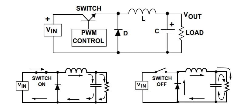
During operation, the input voltage is connected to the inductor, and the difference between the input and output voltages is then forced across the inductor, causing current to increase. During this time, the current flows into both the load and the output capacitor, charging the capacitor. When the switch turns off, the capacitor discharges into the load, contributing to the total current – the sum of the inductor and capacitor current – being supplied to the load.

How It Works: The Boost Converter
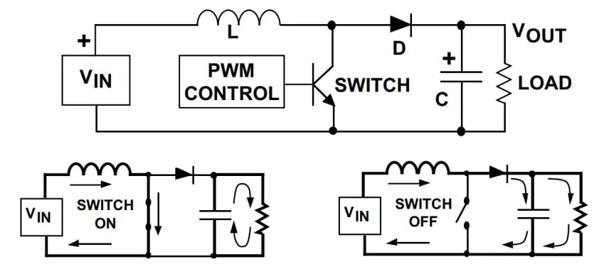
Conversely, a boost converter takes a DC input voltage and produces a DC output voltage that is higher in value than the input, but of the same polarity. When the switch is turned on, the input voltage is forced across the inductor, causing the current to ramp up. When the switch turns off, the decreasing inductor current forces the switch end of the inductor to swing positive, forward biasing the diode and allowing the capacitor to charge up to a voltage that is higher than the input voltage. During steady-state operation, the inductor current flows into both the output capacitor and the load during the switch off time. When the switch is on, the load current is supplied only by the capacitor.

Why are Capacitors an Important Component in Buck and Boost Converters?
Good engineering practice requires that additional external capacitance be placed at the input and output of all regulators. This is because capacitors not only help reduce voltage ripple and improve reliability, but these components also increase efficiency compared to linear regulators. A well-designed power supply decoupling network will employ different types of capacitors made from different materials such as ceramic, aluminum, and tantalum.
The Benefits of Using Multilayer Ceramic Capacitors in Converters
Choosing the right capacitor for your converter is a key decision to ensuring your final product is as efficient, durable, and reliable as possible. Multilayer ceramic capacitors (MLCCs) are especially helpful since these capacitors provide several layers in a single component, delivering a capacitance level equivalent to using multiple single-layer capacitor (SLCs) connected in parallel.
MLCCs can often be used as the following components that may be included in a buck or boost converter:
- Optional input filters – When the frequency is less than 1MHz, MLCCs can be placed in parallel with either a Bulk Aluminum Electrolytic or Polymer Capacitor for maximized filtering. Meanwhile, when the frequency is greater than MHz, MLCCs are more ideal filters.
- Bypass capacitors - Eliminates voltage droops on the power supply by storing an electric charge that can be released when a voltage spike occurs.
- Snubber capacitors – MLCCs help reduce ripple in a switching network.
- Output capacitors – Low-value ceramic capacitors (<1uF) can be used when the frequency is greater than 1 MHz, or aluminum electrolytic when the frequency is less than 1 MHz.
Using MLCCs in these components can help improve ripple-current rating, filtering performance, and longevity for a converter. MLCCs are versatile and are a good option for anything ranging from a simple topology to the more complicated.
Special Considerations for High-Reliability Applications
For applications requiring high reliability – for example, a military drone’s power supply – additional testing to military standards (MIL-STDS) must be met. When choosing a capacitor for a high-reliability application, it is important to select components that meet more rigorous MIL-STD requirements including being burnt in at elevated voltage and temperature levels and undergoing 100 percent electrical inspections to ensure conformance with strict performance criteria. This will ensure your components are qualified for use in even the most sophisticated and secure military and aerospace applications.
Providing Additional Expertise for Implementing Boost and Buck Converters
Knowles Precision Devices employs a highly experienced Applications and Product team that can help you choose the right capacitors for your buck and boost converters or even the more complicated DC-DC converter topologies as mentioned above. As an expert in developing MLCCs and power supply applications, our components are thoroughly tested to the most stringent levels to ensure reliability, accuracy, and success for our customers.
Size out your capacitator using our online Part Builder Tool. Need additional system design support? We can help with that too. Contact us now.

