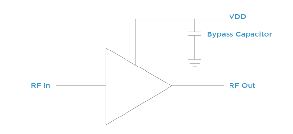
Supply noise creates challenges in RF systems where it can mix with RF signals, impacting signal-to-noise ratios and potentially causing spurious output. Thus, high-frequency monolithic microwave integrated circuit (MMIC) amplifiers with broadband gain need to be protected from RF noise on the supply lines. Avoiding these issues with supply line noise requires RF designers to use a bypass capacitor that provides an efficient path to ground for RF energy on the supply line before it enters a gain stage (Figure 1).

Figure 1. Bypass capacitor in shunt to the gain stage supply line.
To do this effectively without allowing noise into the system, a truly broadband approach to noise filtering bypass circuits is needed. However, bypassing a system with wide bandwidth requires careful analysis to select the right capacitor.
First, many MMICs designed for high frequencies, especially in the military and defense industry, use a wire-bond manufacturing approach rather than a surface-mount approach. Thus, capacitors used for these applications need to provide the right amount of capacitance at high enough operating voltages in a package optimized to provide a clean connection for a wire-bonded MMIC.
Furthermore, wire-bondable microwave capacitors are placed on the ground plane as close to the MMIC device as possible. Depending on the frequency range that needs blocking, one or two microwave capacitors can be used. When a pair of Microwave capacitors are used it is common to see 100pF Border Cap® close to the MMIC and a 10nF V-Series as the second device (Figure 2).

Figure 2. Examples showing a design with one or two microwave capacitors in use.
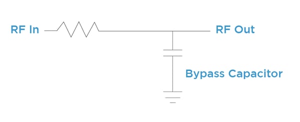
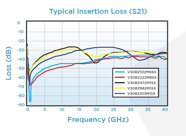
Additionally, when deciding which capacitor will work for your application, the system needs to be fully tested in the way it’s going to be used. This means you need to evaluate the impedance of the device over the entire frequency range of interest. In other words, selecting the correct capacitor for your application involves finding a microwave capacitor that provides the required isolation when tested on a board in shunt (Figure 3 and 4).

Figure 3. The cap in shunt to a line.

Figure 4. The RF isolation of Knowles Precision Device’s V-Series capacitor tested in shunt.
In the end, to find the right capacitor for your MMIC, it not only needs to meet basic criteria such as properly fitting your board, it should also provide a high-quality connection that eliminates noise on the supply line across all frequencies of interest.
To discuss the right approach for your MMIC RF bypassing need, contact us today.

