EMI filtering plays an important role in reducing noise that could interfere with other devices; in medical or defense applications, for example, false alarms due to external interference could be detrimental. Here, we will continue our EMI filtering exploration with application and installation considerations. For earlier reading, review EMI filtering basics and filter performance.
Application Considerations for Panel Mount EMI Filters
Thread Size or Head Size?
Thread size has no relevance to the mounting pitch, but it can influence cost. In addition, very small threads are challenging to work with and offer little gain over larger thread sizes.
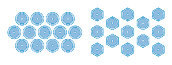
If close mounting pitch is important for the application, select a round body style. Mounted using modified screwdriver blades, the round body style negates the need to allow space for mounting sockets, so components can be mounted almost touching each other. Knowles Precision Devices (KPD) offers a full range of round head filter types - SFKB, SFKK, SFLM and SFUM. Special requirements can also be considered.

Diagram showing the pitch improvement possible with round head filters compared to traditional hexagon heads
Hermetic Seals or Resin Seals?
Resin sealed filters have epoxy encapsulants injected into the cavities around the filter elements to create a durable assembly. The resin supports the pins and seals the ceramic to prevent reliability issues, like moisture ingress; ingress is possible when poor encapsulants crack away from the metalwork due to changes in temperature. Poor encapsulants can also exert a force on the ceramic which can result in cracking and electrical failure. MIL or Space specifications generally do not require that resin sealed filters are tested for immersion or accelerated damp heat testing.
KPD resin sealed filters use a highly filled epoxy encapsulant with high purity and a very low co-efficient of thermal expansion; these characteristics are very close to the expansion co-efficient of the ceramic material itself, and other materials used in the construction. This helps to reduce risk of cracking and moisture ingress by enabling the filter to be thermally cycled with little stress applied to the ceramic elements. Certain KPD filters have successfully passed immersion and accelerated damp heat testing.
Screw mount ‘hermetic’ filters generally have glass to metal seals soldered into place instead of conventional resin seals. Hermetically sealed (glass to metal) solder mount filters are preferred or required over resin seals in applications where one end of the filter will be exposed to harsh environments, or where outgassing is critical on one side of the panel.
MIL or Space specifications generally require that hermetically sealed filters are tested for immersion or accelerated damp heat testing. Unless fitted with sealing rings, the hermetic seal will not provide a gas seal to protect internal capacitor elements. Solder mount hermetic filters may establish a gas seal between either side of the bulkhead, but this is more dependent on the sealing capabilities of the solder joint than the filter seal.
Usually, solder mount filters have a glass seal on one side of the filter body with resin seal on the other; test plans are typically the same as those for resin sealed filters.
Discoidal Capacitor or Tubular Capacitor?
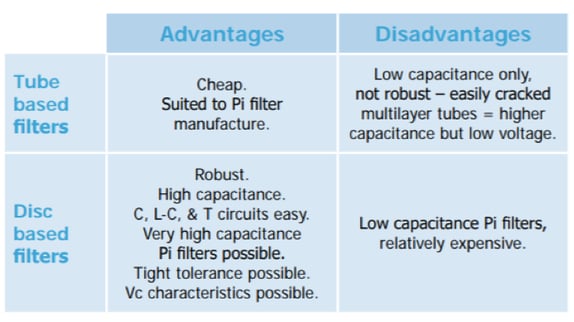
The original panel mount filters used single layer tubular capacitors. These capacitors make for easy Pi filter construction, a primary advantage. For this reason, Pi filters tend to be considered the optimum filter configuration.
With increasing performance demands, came higher capacitance needs. High K, unstable (Z5U / Y5V) dielectrics, and multilayer tubes were employed to meet those demands. Multilayer tubes use buried layer electrodes within the tube walls, but the reduced dielectric thickness resulted in lower voltage withstand capability. The unstable dielectrics cause poor performance over the voltage and temperature ranges. Today, the one significant flaw for tubular capacitors is their thin ceramic walls, making them susceptible to cracking and electrical failures.
As MLCC chip capabilities developed, the discoidal capacitor started to appear in filters; these very low inductance capacitors use MLCC chip technology to achieve improved performance and higher capacitance per unit voltage. They are also physically more robust than tubes.
Most KPD panel mount filters use discoidal capacitors, for optimum mechanical strength, and high quality X7R or C0G/NP0 dielectric materials for optimum electrical performance. However, there are other dielectric materials used in filter manufacturing.

Summary of advantages and disadvantages of disc based and tube based filters
Instillation of Filters
Soldering of Filters
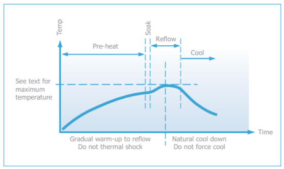
The soldering process should be controlled to prevent the filter from experiencing thermal shocks that could induce thermal cracks in the ceramic dielectric. The pre-heat temperature rise of the filter should be kept to around 2°C per second. In practice, successful temperature rises are typically in the region of 1.5°C to 4°C per second, depending on substrate and components. Introducing a soak could prevent substrate warping by allowing for temperature uniformity across the substrate. Warping can impose damaging stresses upon the filter depending on the magnitude or direction.

Recommended soldering profile
E01, E03, E07 SBSP ranges are compatible with all standard solder types including lead-free, maximum temperature 260°C. For SBSG, SBSM and SFSS ranges, solder time should be minimized with a maximum temperature controlled at 220°C. For SFSR, SFST, and SFSU ranges, the maximum temperature is 250°C.
Cooling to ambient temperature naturally allows for a gradual relaxation of thermal mismatch stresses in the solder joints. Draughts should be avoided; forced air cooling can induce thermal breakage, and cleaning with cold fluids immediately after a soldering process may result in cracked filters.
Resin Filled Screw Mounted EMI Filters
The ceramic capacitor, the heart of the filter, can be damaged by thermal and mechanical shock and over voltage. Minimizing risk of stress during installation (mounting and soldering) is paramount.
Mounting to Chassis
Mounting Torque: To avoid distorting the case and damaging the capacitor, it is important to mount the filter to the bulkhead or panel using the recommended mounting torque. When a threaded hole is used, the maximum mounting torque should be 50% of the specified figure for unthreaded holes.
Tools: Hexagonal devices should be assembled using a suitable socket. Round bodied filters may be fitted to the panel in one of two ways (and should not be fitted using pliers or other similar tools which may damage them):
- Round bodies with slotted tops are designed to be screwed in using a simple purpose-designed tool.
- Round bodies without slotted tops are intended to be inserted into slotted holes and retained with a nut. The thread has flats machined to engage with the flats in the hole.
Grounding: The filter body should be adequately grounded to the panel to allow an effective path for the interference and ensure proper operation. The use of locking adhesives is not recommended, but if used, it should be applied after the filter has been fitted.
Minimum plate thickness: A majority of these filters have an undercut between the thread and the mounting flange of the body that is equal to 1.5 times the pitch of the thread. Mounting into a panel that is thinner than the undercut length may result in problems with thread mating and filter position; use a panel thicker than the undercut length wherever possible.
Maximum plate thickness: Plate thickness is specified for each filter so the nut can be fully engaged, even when using a washer.
Soldering to Axial Wire Leads
|
|
Recommendation |
|
Soldering temperature |
The tip temperature of the iron should not exceed 300°C. |
|
Dwell time |
Dwell time should be 3-5 seconds maximum to minimize the risk of cracking the capacitor due to thermal shock. |
|
Heat sink |
Where possible, a heat sink should be used between the solder joint and the body, especially if longer dwell times are required. |
|
Bending or cropping of wire leads |
Bending or cropping of the filter terminations should not be carried out within 4mm (0.157”) of the epoxy encapsulation, the wire should be supported when cropping. |
Note: Soldering irons should not be used for mounting surface mount filters as they can result in thermal shock damage to the chip capacitor.
RoHS Compliance: All surface mount filters, resin sealed panel mount filters, and power filters can be supplied, fully RoHS compliant (2011/65/EU), through material exemption. Extra care should be exercised to avoid exceeding the maximum soldering temperatures of surface mount parts.
Standard hermetic sealed panel mount filters use SnPb solders as part of their assembly and are intended for exempt applications, including aerospace and military. Substitution of the SnPb solder with Pb free solders may be possible to create a RoHS compliant part, subject to quantities.
For more information on application and installation considerations and expert consulting on filter selection, contact us or explore our site.

