Welcome to the Capacitor Fundamentals Series, where we teach you about the ins and outs of chips capacitors – their properties, product classifications, test standards, and use cases – in order to help you make informed decisions about the right capacitors for your specific applications. After describing factors that affect capacitance in our previous article, let’s discuss dielectric polarization and its relationship with frequency
What is Dielectric Polarization?
When an electric field is applied to a capacitor, the dielectric material (or electric insulator) become polarized, such that the negative charges in the material orient themselves toward the positive electrode and the positive charges shift toward the negative electrode. Since charges are not free to move in an insulator, the polarization effect that opposes the applied field draws charges onto the electrodes, thus storing energy in the capacitor.
The more easily a material be polarized, the greater the amount of charge can be stored in the capacitor. This ability to store energy in an electric field is referred to as the dielectric constant K, or relative permittivity εr. The degree of polarization P is related to the dielectric constant K and the electric field strength E as follows:
P = ε0(K-1) E
where ε0is a physical constant known as the vacuum permittivity
The total polarization of a dielectric comes the sum of four sources of charge displacement: electronic displacement Pe, ionic displacement Pi, orientation of permanent dipoles Pd, and space charge displacement Ps.
Pt= Pe+ Pi+ Pd+ Ps
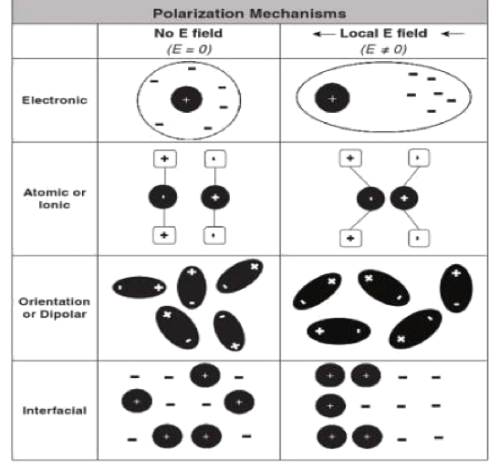
Figure 1. Four types of polarization mechanisms (source: ACRHEM)
Electronic Polarization: This effect occurs in all atoms under the application of an electric field. The nucleus of the atom and the center of its electron cloud shift away from each other, creating a tiny dipole with very small polarization effect.
Ionic Polarization:In ionic solids such as ceramic materials, the ions are symmetrically arranged in a crystal lattice with a net zero polarization. Once an electric field is applied, the cations and anions are attracted to opposite directions. This creates a relatively large ionic displacement (compared to electronic displacement), which can give rise to high dielectric constants in ceramics popularly used in capacitors.
Dipole (or Orientation) Polarization: Certain solids have permanent molecular dipoles that, under an electric field, rotate themselves in the direction of the applied field, creating a net average dipole moment per molecule. Dipole orientation is more common in polymers since their atomic structure permits reorientation.
Space Charge (or Interfacial) Polarization: In ceramics, this phenomenon arises from extraneous charges that come from contaminants or irregular geometry in the interfaces of the polycrystalline solids. These charges are partly mobile and migrate under an applied field, causing this extrinsic type of polarization.
How Does Frequency Affect Polarization and Dielectric Loss?
Interestingly, each type of polarization has a different time response capability to an applied field frequency, which means the net effective of polarization to the dielectric constant is frequency dependent.
- Electronic displacement is very rapid, so this polarization occurs at frequencies of up to 1017
- Ionic polarization is a bit slower and occurs at frequencies up to 1013
- Dipole polarization occurs at frequencies less than 1010
- Space charge polarization is the slowest and occurs at less than 104
Therefore, the dielectric constant (and therefore the capacitance value) always decreases with increased frequency, since the polarization mechanisms become less effective.
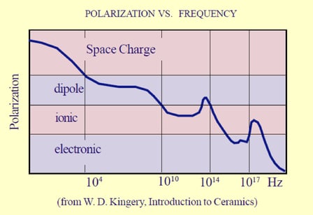
Figure 2. Effect of frequency on polarization mechanisms
In an AC circuit, the voltage and current across an ideal capacitor are 90degrees out of phase. However, real-world dielectrics are not perfect, and therefore the lag or “relaxation time” of the polarization mechanisms with frequency generates dielectric losses. The angle by which the capacitor’s current is out of phase from the ideal can be determined, and the tangent of this angle is a material property called the loss tangent (Tan δ) or dissipation factor. In practice, materials with higher dielectric constants (and therefore high polarization mechanisms) display higher dissipation factors.
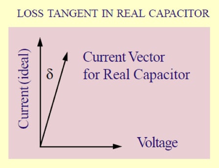
Figure 3. Tangent loss or dissipation factor of a real-world capacitor
The frequency at which a dielectric is used has an important effect on the polarization mechanisms, notably the relaxation time displayed by the material when following field reversals in an alternating circuit.
- Case 1: If the relaxation time for polarization is much longer and slower than the field reversals, the ions cannot follow the field at all and losses are small.
- Case 2: If the relaxation time is much faster than the field reversals, the polarizing processes can easily follow the field frequency and losses are small.
- Case 3: If the relaxation time and field frequency are the same, the icons can follow the field but are limited by their lag, thus generating the highest loss with frequency.
Therefore, dielectric losses are highest at the frequency where the applied field has the same period of the relaxation process. Ceramic dielectric formulations always show a range of relaxation times over the frequency spectrum, since these materials consist of polycrystalline matter. In high frequency applications, this parameter is often known as the Q factor, which is the reciprocal of the loss tangent: Q = 1 / (tan δ)
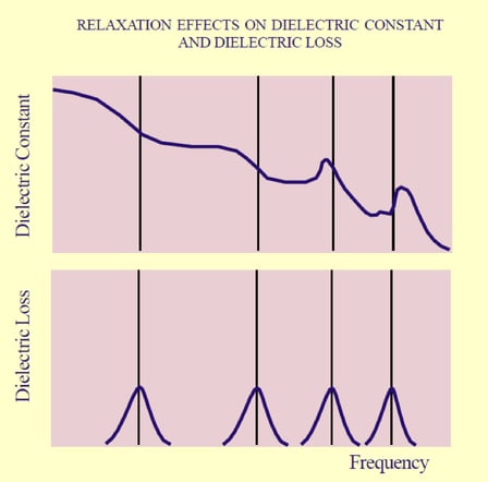
Figure 4. Changes in dielectric constant and dielectric loss caused by frequency
Hopefully, Part 4 gave you a better understanding of the dielectric polarization and how it affects your specific application. In Part 5, we’ll be covering dielectric properties such as insulation resistance and dielectric strength. Also, check out our Knowles Precision Devices Capacitors to view our complete product offering.
To learn more about capacitors, download our ebook, A Guide to Selecting the Right Capacitor for Your Specific Application.