Welcome to the Capacitor Fundamentals Series, where we teach you about the ins and outs of chips capacitors – their properties, product classifications, test standards, and use cases – in order to help you make informed decisions about the right capacitors for your specific applications. After describing linear dielectrics in our previous article, let’s discuss the different types of dielectrics.
Different dielectric materials all have their own characteristics and practical uses. Generally speaking, there is a trade-off such that dielectrics with a higher dielectric constant K have greater losses and less stability in terms of temperature, voltage, and time. Dielectric formulations are classified in the industry by their temperature coefficient of capacitance (TCC), or how much capacitance changes with temperature. Class I and II are commonly used for making ceramic chip capacitors, while Class III is used for making disc capacitors.
Class I Dielectrics
Class I dielectrics comprise of non-ferroelectric, linear dielectrics, which display the most stable characteristics and have dielectric constants under 150. Class I also includes a subgroup of “extended” temperature compensating ceramics using small additions of ferroelectric oxides (such as CaTiO3 or SrTiO3) that display near-linear and predictable temperature characteristics with dielectric constants ranging up to 500. Both groups are commonly used in circuitry requiring stability of the capacitor because of characteristics such as:
- Little to no aging of the dielectric constant
- Low loss such that the dissipation factor (DF) is less than 0.001 or less than 0.002 for extended temperature compensating ceramics
- Little to no change in capacitance or dielectric loss with voltage or frequency
- Predictable linear behavior with temperature within prescribed tolerances
The Electronic Industries Association (EIA) Standard 198 defines a letter-number-letter code to describe the temperature coefficient of Class I dielectrics as follows: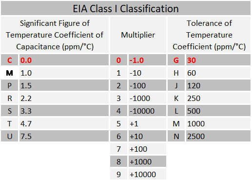
Table 1. EIA Designations for Class I Dielectrics
The most common Class I dielectric for chip capacitors is the C0G designation (emphasized with red text in Table 1) and is also known as NP0 (negative-positive-zero) in the U.S. military (MIL) specification for its flat temperature coefficient. It has an allowable capacitance change of ±30 ppm/°C over the -55°C to 125°C operational temperature range.
C0G is stable with voltage, has negligible aging, and has a DF at a maximum of 0.15% (which is less than the X7R dielectrics that are described below). When operating at high frequencies, this lower DF means that the power lost in the capacitor is reduced and the component is less prone to overheating. In general, C0G dielectrics have K values of between 20 to 100 and are used to make stable, lower capacitance parts in the picofarad (pF) to nanofarad (nF) region. They are typically used for filtering, balancing, and timing circuits.
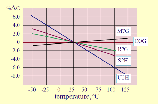
Figure 1. Temperature coefficients of linear dielectrics
Class II Dielectrics
Ferroelectric formulations are categorized as Class II dielectrics. They offer much higher dielectric constants than Class I dielectrics, but have less stable properties with regards to temperature, voltage, frequency, and time. The diverse range of properties of the ferroelectric ceramics is split into two subgroups, defined by the temperature characteristics:
- “Stable Mid-K” Class II dielectrics have a maximum temperature coefficient of ±15% from the 25°C reference over the temperature range of -55°C to 125°C. These materials typically have dielectric constants from 600 to 4000 and meet the EIA X7R characteristics (see Table 2 below).
- “High K” Class II dielectrics have temperature coefficients exceeding the X7R requirements. These high K formulations have dielectric constants from 4000 to 18,000 but with very steep temperature coefficients (due to the fact that the Curie point is shifted towards room temperature for maximum dielectric constants).
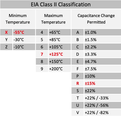
Table 2. EIA Designations for Class II Dielectrics
X7R (emphasized with red text in Table 2) is one of the more commonly used Class II dielectrics. The ‘X’ and ‘7’ define the lower and upper operational temperature range (i.e., -55°C and +125°C respectively). The ‘R’ defines the stability within the temperature (i.e., ±15% tolerance). The DF is a maximum of 2.5%, and the aging rate for X7R is about 1% to 2% per time decade (which means that, at 1% aging, 2% of the capacitance value will be lost between hour 10 and hour 1000). X7R has a high K value of around 3000 and is used for capacitance values in the nF to microfarad (µF) range. With these characteristics, X7R are commonly found in energy storage, smoothing, and filtering applications.
The U.S. military specification for ceramic chip capacitors (MIL-C-55681) also falls in the Stable Mid-K subgroup and is designated as “BX.” In effect, the BX characteristic is similar to the X7R designation, as long as the voltage coefficient and temperature coefficient combined do not exceed +15% -25%ΔC. Figure 2 shows some typical Class II temperature coefficient curves as an example.
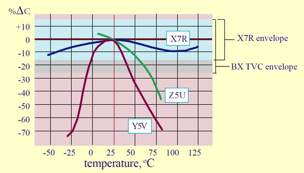
Figure 2. Temperature coefficients of ferroelectric dielectrics
Hopefully, Part 8 gave you a better understanding of dielectric classifications and how their properties may affect your specific application. In Part 9, we’ll be diving into capacitor test parameters and electrical properties. Also, check out our Knowles Precision Devices Capacitors to view our complete product offering.
To learn more about capacitors, download our ebook, A Guide to Selecting the Right Capacitor for Your Specific Application.


