

Temperature stability, equivalent series resistance (ESR), and physical construction all influence how a capacitor behaves in an LC tank circuit.
Class I capacitors are made from ceramics that are significantly less sensitive to temperature. With an allowable capacitance charge of ± 30 ppm/°C over the -55 °C to 125 °C operating range, Class I dielectrics are the most common material for chip capacitors in the C0G and NP0 designations.
Class II dielectrics use ferroelectric formulations with higher dielectric constants than Class I types, but their properties are less stable across temperature ranges (Figure 1). X7R is one of the more common Class II dielectrics. Class II capacitors can experience a decrease in capacitance versus bias voltage, so Class I capacitors are preferred for stability over input voltage ranges.
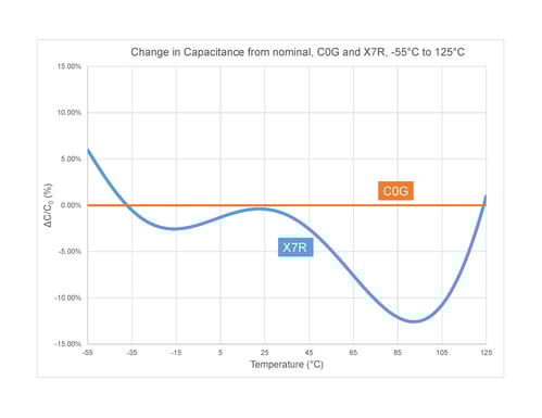 Figure 1: Temperature stability comparison between C0G and X7R dielectric capacitors. C0G remains virtually unchanged across the full range.
Heat is a major concern in resonant circuits. Higher ESR causes additional losses, generating heat that can compromise long-term reliability. One way to combat this is to implement lower ESR capacitor types, like Class I. From a construction standpoint, consider electrodes and even case size; larger case sizes can tolerate high power because they cool better.
When a resonant tank circuit requires high capacitance, it may be necessary to build custom assemblies to reach that capacitance at high power. Knowles offers a broad range of capacitors for different energy storage needs. For detailed specs, review What Kind of Capacitors Does Knowles Make?