To help customers with filter selection, we generally provide a lot of information on what our filters can do. But in this new Filter Basics Series, we are taking a step back to cover some background information on how filters do what they do. Regardless of the technology behind the filter, there are several key concepts that all filters share that we will dive into throughout this series. By providing this detailed fundamental filter information, we hope to help you simplify your future filtering decisions.
In part 3 of this series, we aim to help simplify filter selection by providing an overview and reference point for five of the most commonly discussed filter technology specifications.

To select the ideal filter for your application, you first need to understand how to define your filtering requirements as these requirements will ultimately determine the specifications of your filter. While there are many possible filter specifications, this post covers the following five key specifications we feel are crucial to understand:
- Center frequency
- Bandwidth
- Insertion loss
- Out-of-band rejection
- Selectivity
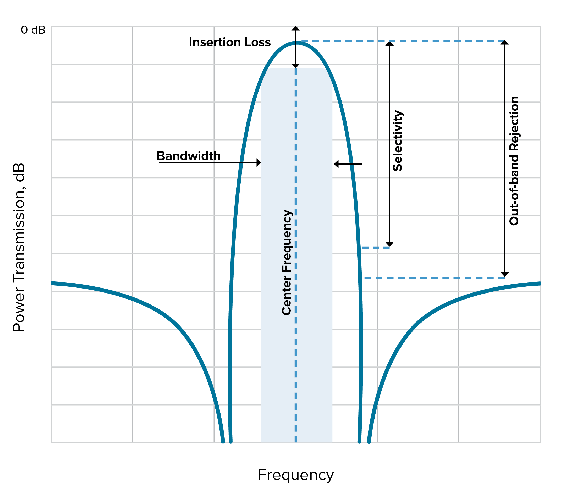
In Figure 1, you can see each of these five metrics called out on a plot for a typical bandpass filter response.

Figure 1. An example of a typical bandpass filter response with the five key filter specifications we are examining called out.
Let’s dive into each of these specifications in more detail.
Center Frequency
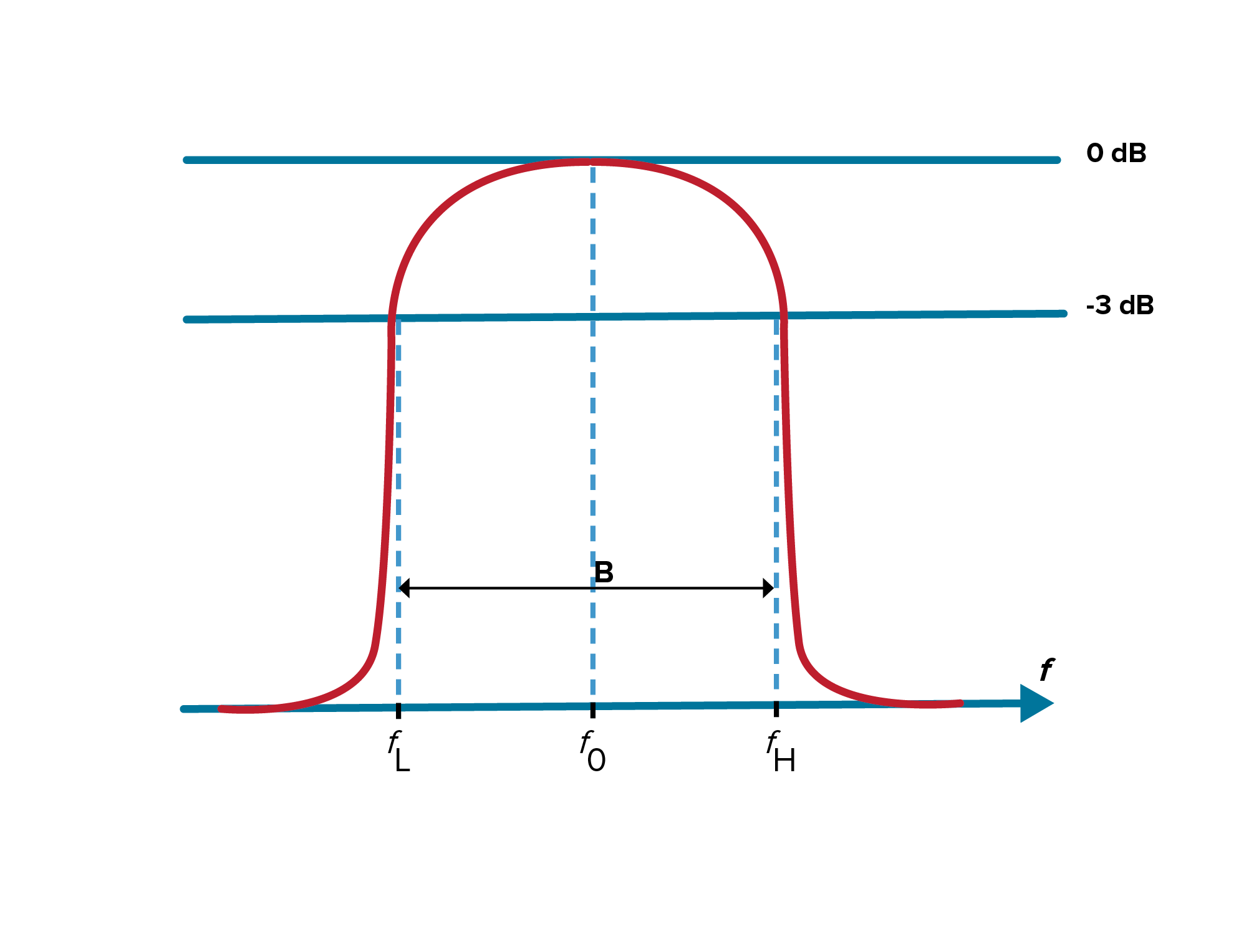
Center frequency is defined as the geometric or arithmetic mean of the upper and lower cutoff frequencies or 3dB points of the bandpass filter. The center frequency in the example in Figure 2 is identified as f0.

Figure 2. In this example, fL is the lower cutoff of this bandpass filter while fH is the upper cutoff, therefore, f0 is the center frequency.
Bandwidth
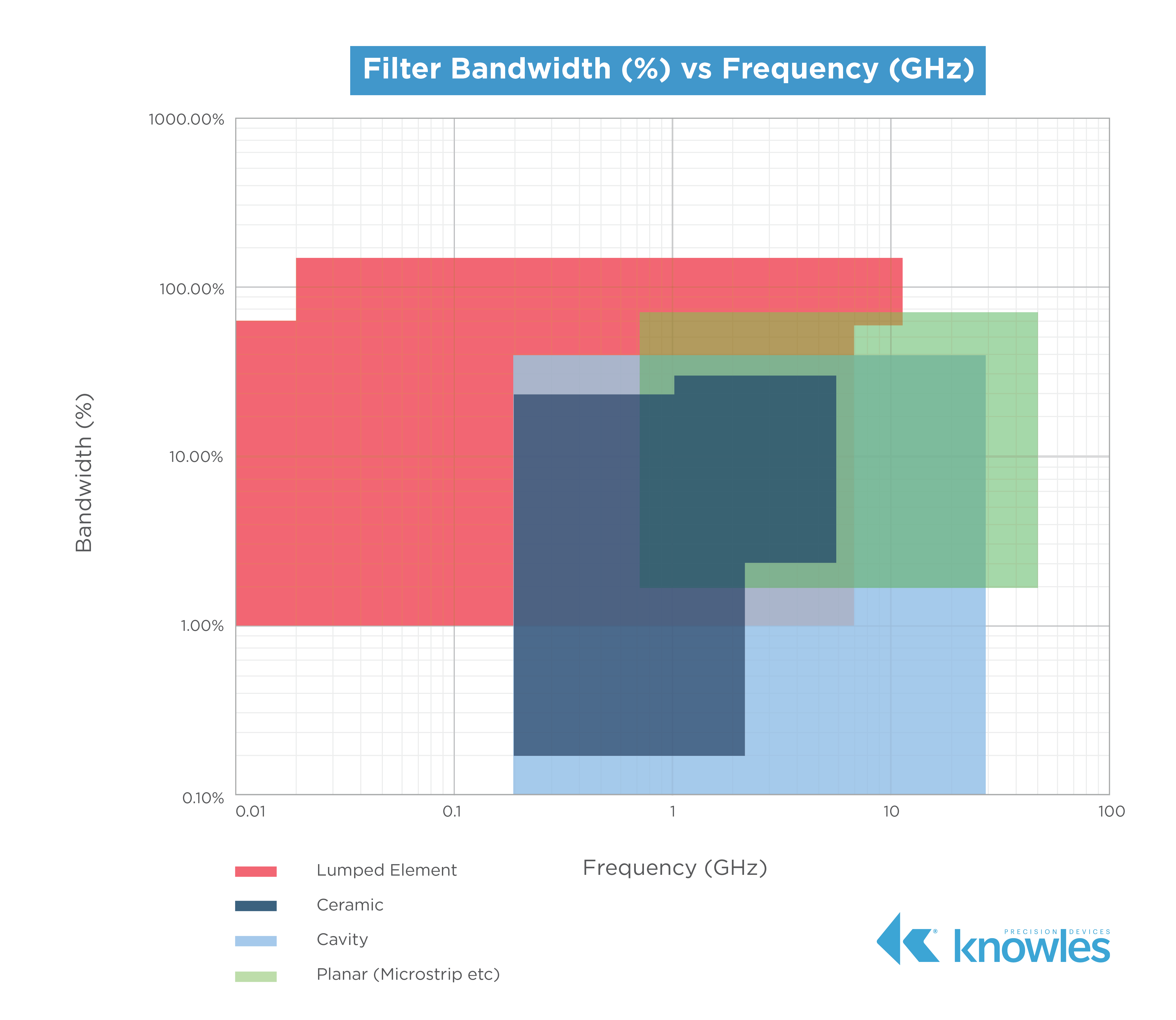
Bandwidth is the width of the passband of the bandpass filter and is expressed as the frequency difference between the lower and upper 3 dB points. When it comes to bandwidth, we can also look at the relative or fractional bandwidth of the filter, which is the ratio of a filter’s bandwidth to its center frequency. As shown in Figure 3, different filter technologies are capable of different fractional bandwidths.

Figure 3. This graphic shows fractional bandwidths across frequencies for a variety of filter types.
As you can see in Figure 3, it is possible to have a fractional bandwidth that is greater than 100 percent. For example, if your filter has a 2 – 18GHz range, the center frequency is 10GHz and the bandwidth is 16GHz, which would make the fractional bandwidth 160 percent.
Insertion Loss
Insertion loss is the ratio of a signal level in a test configuration without a filter present (|V1|) to that when the filter is present (|V2|) and is calculated as shown in the equation below.

It is important to note that you should consider insertion loss as a specification on both the Tx side since power is a system cost driver, as well as on the Rx side because loss impacts the overall noise figure of the receiver.
Out-of-Band Rejection
A passband filter cannot allow interference from signals outside the bandwidth of interest. Therefore, your filter needs to have the ability to reject (attenuate) out-of-band emissions. These out-of-band emissions are far away from the band of interest (refer back to Figure 1) but can still interfere with the signals within the passband through effects such as aliasing. More specifically, in their recommendation document on “Unwanted Emissions in the Out-of-Band Domain,” the International Telecommunications Union (ITU) defines out-of-band emissions as “Emission on a frequency or frequencies immediately outside the necessary bandwidth which results from the modulation process, but excluding spurious emissions.”
Selectivity
Selectivity is a measurement of a filter’s ability to pass or reject specific frequencies closer to the band of interest. Selectivity is also sometimes described by talking about the size of the transition band necessary to get from the pass band to a certain rejection level, and often the size of the transition band is expressed as a percentage of the center frequency. Thus, a filter’s selectivity can tell us how much of the total bandwidth needs to be dedicated to transition bands.
If a filter has high selectivity, smaller transition bands are needed, which means smaller guard bands are necessary and less bandwidth is wasted implementing these features. Therefore, high selectivity is crucial in environments where adjacent channels are close together as high selectivity enables RF system designers to most efficiently use the available bandwidth. Additionally, selectivity is a critical specification for determining a filter’s suitability for a given application because a system’s transmission and reception characteristics are given in terms of both insertion loss in the pass band as well as clearly prescribed attenuation requirements in the stop band.
Putting it All Together: A Real-World Filter Example
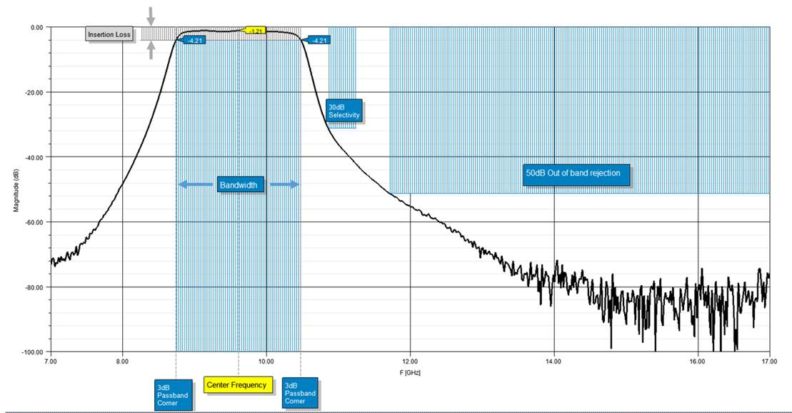
While we started this post with a hypothetical example of based on typical bandpass response with, Figure 4 shows these five specifications called out on an S21 plot for one of our 9.5GHz surface-mount bandpass catalog filters, B095MB1S.

Figure 4. These five key specifications identified on an S21 plot of one of our popular filters.
Now that you have an overview of some of the key filter specifications, you are ready for  of our Filter Basics Series where we will dive into the details of a variety of common filter types. In the meantime, visit our
  to check out the other posts in this multi-part series or take a deeper dive in the fundamentals of RF Filters by downloading the comprehensive Filter Basics guide today.


