
To help customers with filter selection, we generally provide a lot of information on what our filters can do. But in this new Filter Basics Series, we are taking a step back to cover some background information on how filters do what they do. Regardless of the technology behind the filter, there are several key concepts that all filters share that we will dive into throughout this series. By providing this detailed fundamental filter information, we hope to help you simplify your future filtering decisions.
In part 4 of this series, we provide overviews of the main filter types and key filter technologies available today.
To choose the right filter for your application, you first need to have a solid understanding of how to evaluate filter types and identify the specific filter technology that will best suit your application.
Filter Types
To start, there are four filter response types that can be used to define the frequencies that will be removed or allowed by the filter.
Low Pass
Low pass filters allow frequencies below a given frequency to pass (be transmitted or received) while rejecting frequencies above the given frequency.
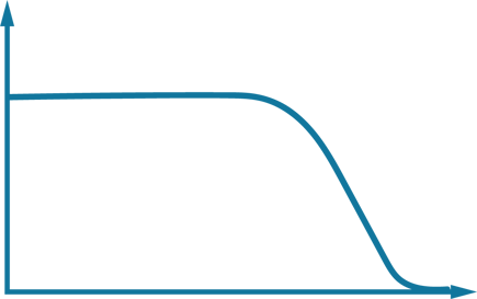 Figure 1. An illustration of a how a low pass filter works.
High Pass
High pass filters function in the opposite manner of a low pass filter. High pass filters let frequencies above a given frequency pass through the filter while rejecting frequencies below the given frequency.
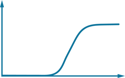 Figure 2. An illustration of a how a high pass filter works.
Band Pass
Band pass filters pass frequencies between two frequencies (set upper and a lower limits) while rejecting all other frequencies.
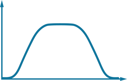
Figure 3. An illustration of a how a band pass filter works.
Band Stop
Band stop filters, which are also known as band reject or notch filters, function in the opposite manner of a band pass filter. Band stop filters prevent all frequencies between two frequencies from passing while allowing all others to pass.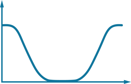
Figure 4. An illustration of a how a band stop filter works.
Filter Technologies
Beyond determining the filter type you will need, you also need to identify the specific filter technology that best suits your application. Let’s review the common filtering technologies shown in Figure 5, including the frequencies and bandwidths each technology is best suited for.
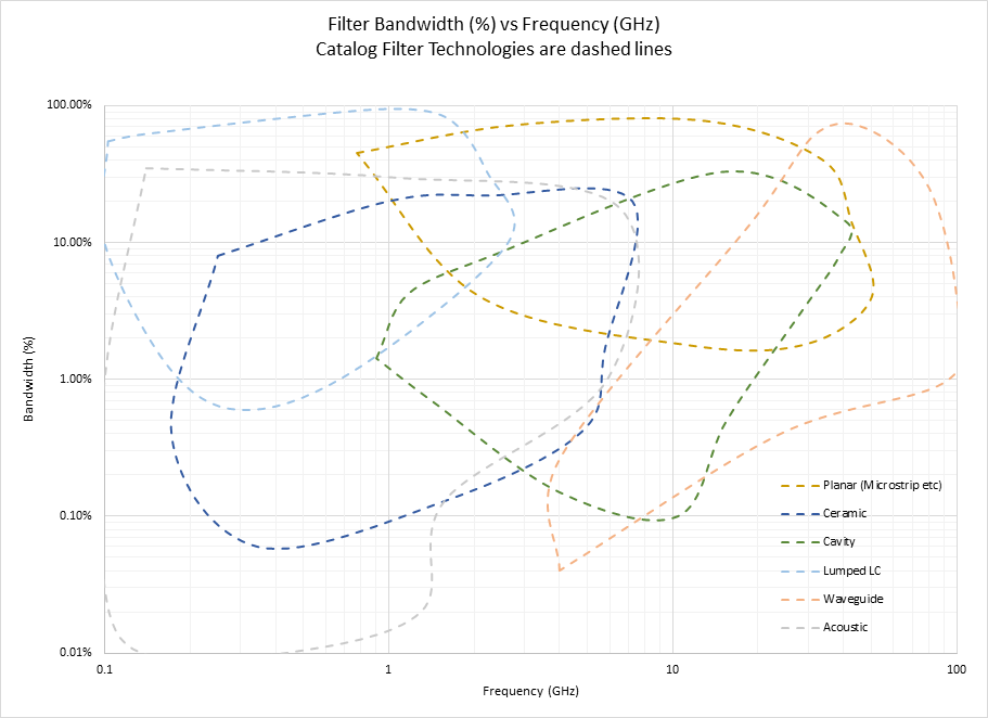
Figure 5. A map of filter technology performance across the frequency spectrum.
Lumped Element
Thinking back to part 1 of this series, lumped element filters are passive filters that consist of the appropriate series of inductors (Ls), capacitors (Cs), and resistors (Rs) for your application. Building a lumped element filter using a discrete LCR approach provides a low-cost way to implement a filter, but the attainable Q factor is limited. Discrete lumped element filters are usually used in the 30 MHz to 300 MHz range but can be built for applications up to 40 GHz. However, discrete lumped element filters are hard to implement at mmWave frequencies because of the dimensional limitations imposed by the frequency since the filter elements must be much smaller than the wavelength of the transmission lines. Discrete LCR designs are also performance and repeatability limited by the tolerances of the discrete components.
Acoustic
Acoustic filters have two variations – surface acoustic wave (SAW) and bulk acoustic wave (BAW). Acoustic filters are unique because these filters convert the AC electrical signal they are meant to process into acoustic waves. Filtering is done on the acoustic waves by allowing certain waves at the right frequency to travel through the device. Then, the acoustic signal is converted back into an AC electrical signal for transmission.
This technology is ingenious because the signal is filtered at a much lower speed, which means smaller wavelengths, and this translates into the ability to be able to design very small filters. We will re visit the benefits of changing the speed of the wave travelling in a filter, especially for much higher frequencies like those at mmWave, when we touch on the transmission line-based microstrip later in the post. Additionally, since acoustic filters cover a range of frequencies up to 6 GHz and offer a good performance/cost tradeoff, this has made these filters the dominant off-chip filter approach in mobile devices today.
Ceramic Filters Based on Coaxial Ceramic Resonators
Ceramic filters cover a range of ~100 MHz to ~8 GHz. These filters offer similar performance to discrete lumped element LC designs but can be implemented in small-form-factor surface mount packages. Performance and package thickness can be a limiting factor of this filter type compared to developing acoustic filters with SAW/BAW technology.
Cavity
Cavity filters can be used up to 30GHz and can offer high selectivity and narrow bandwidth under high power. Cavity filters can achieve good performance but are physically large and usually only seen in infrastructure applications, such as for additional filtering at a cell site.
Transmission Line-Based Microstrip
At a high level, a microstrip filter is a type of distributed element planar transmission line that is simple to implement in printed circuit boards (PCBs). Composed of a strip conductor, dielectric substrate, and ground plate, microstrip is used in the microwave range with a typical maximum frequency of 110 GHz. The biggest concern with this filter type is the loss experienced compared with other transmission-line and waveguide filtering approaches. However, the evolution of high-k materials, such as Knowles Precision Devices’ PG, CF, and CG, is making it possible for RF engineers to develop low-loss microstrip transmission-line filters.
Waveguide
Waveguide filters are constructed using waveguide technology, which is a structure that guides waves with minimal loss. In general, the main advantages of a waveguide filter include high Q factor, which occurs by using air as a dielectric, high power capacity, and near-zero loss. A primary disadvantage of waveguide filters is the relative size of these structures compared to filters that use a transmission line and can take advantage of transverse electromagnetic (TEM) modes.
Now that you have a high-level understanding of filter types and technologies, you are ready for  where we will dive into more details on how lumped element and distributed element filtering approaches work as well as when it is best to use each approach. Visit our
  to check out the other posts in this multi-part series or take a deeper dive in the fundamentals of RF Filters by downloading the comprehensive Filter Basics guide today.