To choose the right filter for your application, you'll need to evaluate filter type, identify the specific filter technology that best suits your application, and ensure the filter meets your required specifications. This post is designed to serve as a quick reference on the common terms that are used to discuss filter type, technology, and specifications.
To start, there are four key Filter behaviors that sort them into types: Low Pass, High Pass, Band Pass, and Band Stop.
Filter Types
| Low Pass filters allows frequencies below a given frequency to pass (to be transmitted or received) while rejecting frequencies above the given frequency. | 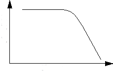 |
| High Pass filters let frequencies above a given frequency to pass through the filter, while rejecting frequencies above the given frequency (opposite of low pass). | 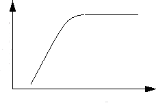 |
| Band Pass filters pass frequencies between two frequencies while rejecting all others. |  |
| Band Stop (or Band Reject) filters prevent all frequencies between two frequencies from passing while allowing all others to pass (opposite of band pass). | 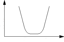 |
Filter Technologies
Crystal Filters
Crystal Filters make use of a quartz crystal as the resonant element. The high Q of a quartz resonator makes for a very steep band-pass. These filters are usually implemented at IF frequencies in the range of 10 MHz and Q factors fall in the range of 10,000 to 100,000.
SAW/BAW (Surface Acoustic Wave and Bulk Acoustic Wave)
Acoustic filters cover a range of frequencies up to 6 GHz and offer a good performance/cost tradeoff, making them the dominant off chip filter approach in mobile devices today.
Ceramic Filters
Ceramic filters cover a range of ~100 MHz to ~8 GHz. They offer similar performance to discrete lumped element inductor-capacitor (LC) designs but can be implemented in small form factor surface mount packages. Performance and package thickness can be a limiting factor when comparing ceramic filters with SAW/BAW.
Lumped Element
Discrete LC approaches provide a low-cost approach to implement a filter, but the attainable Q factors are limited in such devices. Discrete lumped element filters are usually used around the 30 MHz to 300 MHz range but can in principle be built for applications up to 40 GHz. At mmWave frequencies though discrete lumped element filters are very hard to implement because of the dimensional limitations imposed by the frequency, since the filter elements must be much smaller than the wavelength of the transmission lines. Discrete LC designs are performance and repeatability limited by the tolerances of the discrete components.
Cavity
Cavity filters are a common approach in the 40 MHz to 960 MHz frequency range and can offer high selectivity under high power. They can achieve good performance but are physically large, and usually only seen in infrastructure applications, such as for additional filtering at a cell site.
Planar
Planar filters, such as Microstrip filters, are manufactured using a thin-film process, and depending on the filter topology, can offer high Q and a reasonable approach to achieving performance in a small footprint when compared with discrete lumped element designs. In a thin film Lumped Element approach, the filter’s transmission lines are printed in various configurations, depending on the required performance and filter elements are realized through discrete resistive, capacitive, and inductive elements. Planar Distributed Element filters rely on carefully distributed transmission lines to create resonant structures and can be designed to tighter tolerances than a lumped element filter. Distributed Element designs are more practical than Lumped Element designs at increased frequencies.
Waveguide
Waveguide filters are characterized by high power handling capability, leading to their wide adoption in radar applications, high selectivy and rejection and low loss given that the waveguide itself is a low loss medium.
Filter Specifications
Attenuation
Measured in dB, the degree by which a signal sees a loss in amplitude after passing through the filter.
Bandwidth
Bandwidth is the width of the passband of a bandpass filter and is expressed as the frequency difference between lower and upper 3 dB points.
Cut Off
Usually the point at which the response of the filter has fallen by 3dB from passband level.
Group Delay
Group delay is a measure of how different components of a modulated signal (which is a sum of sine waves at various frequencies) would propagate through the filter. Measured in units of time (seconds) and is a derivative of the filter’s phase with respect to frequency.
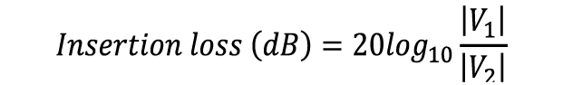
Insertion Loss
Insertion loss is the ratio of a signal level in a test configuration without a filter present (|V1|) to that when the filter is present (|V2|). When discussed this is typically referencing the loss in the passband.
Passband
The Passband is the portion of the frequency spectrum that the filter allows to be transmitted.
Passband Return Loss
The return loss in the filters passband - See Return Loss and Passband.
Percent BW
Percent Bandwidth is a common relative figure of merit that compares bandwidth with carrier frequency. Commonly calculated as 3dBW/(Center Frequency).
Q Factor
The quality factor (Q) of a resonator is expressed as the ratio of stored versus lost energy per oscillation cycle. Overall losses through a resonator increase as Q factor drops and will increase more rapidly with frequency for lower values of resonator Q. As a result, the edges of the passband become more rounded and the bandwidth narrows as the Q decreases.
Rejection
Attenuation of signals outside the passband. Typically measured in dB or dBc if referenced from IL of passband
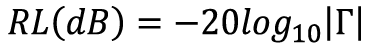
Return Loss
Return loss is a measure of the amount of the signal that is returned or reflected by the filter. Measured in dB, it is the negative of the magnitude of the reflection coefficient expressed as power.
Ripple
Ripple is a measure of the variation of Insertion Loss within the Passband, and is measured in dB.
S11
S11 is the Scattering Parameter that represents the Reflection Coefficient (𝛤) at the input. Related to Return Loss.
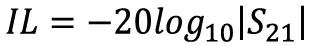
S21
S21 is the Scattering Parameter that (in the case that measurement ports are the same impedance) is a measure of Insertion Loss.
Selectivity
A measurement of the capability of the filter to pass or reject specific frequencies relative to the center frequency of the filter. Selectivity is typically stated as the loss through a filter that occurs at some specified distance from the center frequency. A filter with high selectivity exhibits high slope in the transition from pass to stop – Selectivity is crucial in environments where adjacent channels are close together and high selectivity enables designers to make good use of available bandwidth.
Shape Factor
The ratio of a filters Stop Band to Pass Band. The higher the shape factor, typically the closet the filter is to theoretical performance.
Stopband
The band where the filter has reached its required out of band Rejection
Temperature Stability
Concerns how the temperatures performance varies with temperature. An approach is to define in ppm/°C the shift of the filters, cutoff, passband etc in frequency as temperature varies
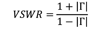
VSWR
A measure of the filters match to a given impedance (e.g. to a 50 Ohm system), Voltage Standing Wave Ratio (VSWR) is calculated from S11 (𝛤).