

To provide a better understanding of build-to-print in general and the breadth of our offerings, as well as how our thin-film technology can benefit your applications, we’ve put together a Build-to-Print Basics series. Part 9 covers the various strategies that can be used for adding vias into circuits.
A via is a small opening in a circuit that allows for a conductive connection between different layers in the circuit or a connection to the ground-plane. In any circuit medium, vias can offer many advantages. However, we often see many designs that overpopulate ground areas as well as poorly placed vias that can degrade yield due to reduced substrate durability in manufacturing. Therefore, it is critical in hard substrate manufacturing to carefully consider via quantity and location.
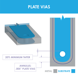
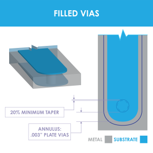
At Knowles Precision Devices, our CAD services can optimize your design by balancing electrical needs with manufacturing enhancements. One of the first determinations we will help you make is if a standard via or a reinforced via – plated or filled – is the best option for your design. Figures 1, 2, and 3 show diagrams of what each via designs looks like and Table 1 provides a high-level overview of the characteristics of plated versus filled vias in an Alumina substrate.
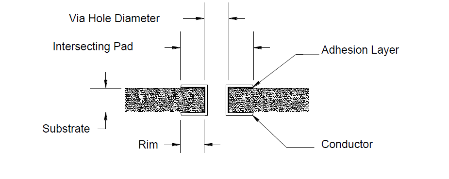
Figure 1. A diagram of a standard via.
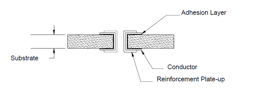
Figure 2. A diagram of a plated via.
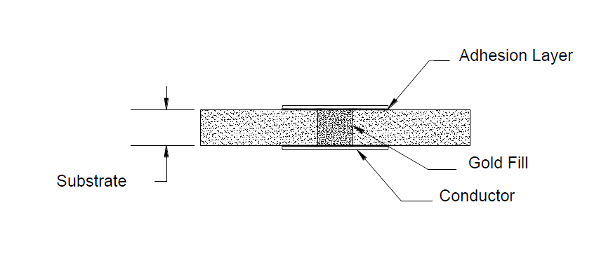
Figure 3. A diagram of a filled via.
Plated Through Vs Filled Vias*
|
Feature |
DC |
Inductance |
RF |
|
|
1 mΩ |
78pH |
4 mΩ |
 |
4 mΩ |
81pH |
14 mΩ |
*Data based on a 0.020" diameter via in a 0.025" thick Alumina substrate.
Table 1. This table provides an overview of the general characteristics of plated vs. filled vias.
An Overview of Our Approach to Plated Vias
For most applications that need plated vias, standard metal thickness through the holes is acceptable. The preferred and allowable diameters for vias on substrates of varying thicknesses are listed in Table 2 below.
Plated Through Via vs. Substrate Thickness
|
Substrate |
Substrate |
Preferred Via |
Allowable Via |
Via Spacing |
|
|
Center-Center |
Center-Edge |
||||
|
.005" |
Al2O3 |
.005" |
.003" - .005" |
.027" |
.023" |
|
.010" |
Al2O3,AIN |
.010" |
.006" - .010" |
.030" |
.025" |
|
.015" |
Al2O3,AIN |
.015" |
.008" - .015" |
.035" |
.027" |
|
.020" |
Al2O3,AIN |
.020" |
.010" - .020" |
.040" |
.030" |
|
.025" |
Al2O3,AIN |
.025" |
.012" - .025" |
.045" |
.033" |
|
.040" |
Al2O3,AIN |
.032" |
.024" - .040" |
.060" |
.040" |
|
.050" |
Al2O3,AIN |
.040" - .050" |
.025" - .050" |
.070" |
.045" |
Table 2. Table 2. This table highlights the characteristics of plated through vias on various substrate thicknesses.
If higher currents are required, the plated via may need to be reinforced. Reinforcement may also be necessary to reduce RF loss in devices such as interdigital band pass filters. This is done through a separate additional processing plating step where we add additional metal in and around the via to give better mechanical strength and lower via hole resistance. Known as selective plating, this process involves the application of different metal systems in selected areas of a circuit or an additional plate of the same metal in selected areas. This could include the addition of a nickel metal layer in an area where solder is required, or it could involve increasing the metal thickness in via walls without using nickel on the resonators for the filters.
An Overview of Our Approach to Filled Vias
One method of enhancing a design, especially if you need to layer components, is to use filled vias. Filled vias provide a good thermal path and ground return path from the top side conductors to the backside ground plane. We use industry-preferred solid Cu and Au processes as opposed to the less-desirable glass/metal paste method used by other companies. Table 3 provides a general overview of via characteristics on substrates of varying thicknesses and materials.
Filled Via Vs Substrate Thickness
|
Substrate |
Substrate |
Ideal Via |
Via Spacing |
||
|
Center – Center |
Center – Edge |
Fill |
|||
|
.010" |
Al2O3 |
.008" |
.028" |
.020" |
Cu,Au |
|
.015" |
Al2O3 |
.012" |
.034" |
.020" |
Cu,Au |
|
.020" |
Al2O3,AIN |
.016" |
.032" |
.020" |
Cu,Au |
|
.025" |
Al2O3,AIN |
.020" |
.040" |
.025" |
Cu,Au |
Table 3. This table highlights the characteristics of plated filled vias on various substrate thicknesses.
Additionally, our process using solid copper-filled vias offers the following advantages versus using solid gold-filled vias:
- Cost effective – 10 to 20 percent cheaper
- Thermal conductivity is 33 percent greater
- Lead time is 20 percent shorter
- Acceptable for prototyping through high-volume production quantities
- Can withstand up to +300°C processing temperatures
- Qualified for use in aerospace applications
In summary, no matter what type of via is needed for your build-to-print design, our team will use the best techniques in the industry to ensure all your requirements are met.
In the next post we will review resistor design guidelines. In the meantime, you can check out the rest of our Build-to-Print Basics series posts to learn more about our build-to-print and thin film offerings or download the comprehensive Build-to-Pring Ebook.
