
To help customers with filter selection, we generally provide a lot of information on what our filters can do. But in this new Filter Basics Series, we are taking a step back to cover some background information on how filters do what they do. Regardless of the technology behind the filter, there are several key concepts that all filters share that we will dive into throughout this series. By providing this detailed fundamental filter information, we hope to help you simplify your future filtering decisions.
Part 5 dives into more detail on lumped element and distributed element filter construction techniques and when each option is most appropriate to use based on your application.
So far, in our Filter Basics Series, we have covered how to make filters out of individual resistors (Rs), inductors (Ls), and capacitors (Cs). Building on this, we also provided the basics of a lumped element filter construction in part 4. In this same post, we gave an overview of several different filter technologies that rely on what is known as a distributed element construction approach. Now in this post, we will expand on these two filter construction approaches and discuss their pros and cons to show when each approach should be used based on your application needs.
Lumped Element Filter Construction
As mentioned in part 4, lumped element filters are passive filters that consist of the appropriate Ls, Cs, and Rs to meet the application’s needs. An example of a generic lumped element structure is shown in Figure 1.
.webp?width=1995&name=Lumped%20Element%20Filter%20(1).webp)
Figure 1. An example of a generic lumped element L-C structure.
Building a lumped element filter using a discrete LCR approach is advantageous for many applications in the 30 and 300 MHz range as this construction method provides a low-cost way to implement a filter. Additionally, lumped element filters are generally easy to design and tune and require minimum tooling costs if the filter is physically smaller than the operating wavelength, allowing for a high degree of customization. This filter construction method is not a good fit for high-power or high-frequency applications though.
At higher operational frequencies, it is hard to achieve narrow bandwidths with lumped element filter construction and parasitics become unpredictable. For example, parasitic capacitance is magnified and will lead to self-resonance, and other parasitic effects from mounting components in the transmission lines can cause the filter to detune at higher frequencies. At the opposite end of the spectrum, L-C filters can also be challenging to design for very low frequencies in the kHz range as well.
Distributed Element Filter Construction
Unlike a lumped element filter, in a distributed element filter design, the elements of the circuit are not localized in discrete Ls, Cs, and Rs. As a result, distributed element filters can be designed to tighter tolerances, which makes this approach a better fit for higher frequency applications. For distributed element filter designs, transmission lines and waveguides are the primary methods used for transferring electromagnetic waves around the circuit. Simply put, a transmission line is a two-conductor structure, and a waveguide is a single conductor with a hollow metal tube that provides distributed inductance with the empty space between providing distributed capacitance. Figure 2 shows examples of how waveguide and transmission lines can be implemented.
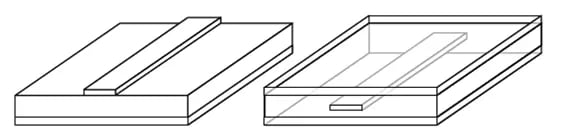
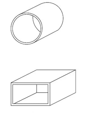
Figure 2. Examples of different transmission line and waveguide filter designs used for distributed-element filters.
The main advantage of a waveguide filter is the high Q factor possible when air is used as a dielectric, which offers high power capacity and near-zero loss. A primary disadvantage of waveguide filters is the relative size of these structures compared to filters that use a transmission line. However, work is being done today to reduce the size of waveguide filters including using ceramic dielectric resonators with a high dielectric constant inside an air-filled waveguide. Using ceramic instead of air reduces the wavelength of the radiation propagating through the material, which consumes less space, but comes at the price of higher losses.
Microstrip and stripline are two common methods used for developing transmission-line-based distributed element filters. Microstrip is a type of planar transmission line that is simple to implement in printed circuit boards (PCBs). Composed of a strip conductor, dielectric substrate, and ground plate, microstrip is used in the microwave range with a typical maximum frequency of 110 GHz. The main concern with using a microstrip approach is that loss compared with other transmission-line and waveguide approaches is high. But high-k materials are evolving that can be used to develop low-loss microstrip transmission-line filters.
Compared to using a microstrip approach, when using a stripline construction, coupled-line structures do not need compensation for unequal phase velocities and there is less radiation. However, Q, manufacturability, and tolerance all decrease when using a stripline versus a microstrip approach. Therefore, stripline is not a great option for building filters for applications that require higher Q and tighter tolerances.
While this post touched on the basics of transmission lines and waveguides, in  we will get into more details on how electromagnetic waves move around inside waveguides and transmission lines and the different modes these approaches can support. Visit our
  to check out the other posts in this multi-part series or take a deeper dive in the fundamentals of RF Filters by downloading the comprehensive Filter Basics guide today.