Passive gain equalizers are designed to rectify or flatten the frequency response of an RF amplifier. RF amplifiers are known to cause a non-uniform gain over the operational bandwidth of a device, which results in distortion and other unwanted effects. Equalizers generate a counter-gain profile to offset that uneven response. Pairing equalizers and amplifiers is critical in applications like broadband systems where consistent performance over a wide frequency range enhances signal fidelity and system performance.
.webp?width=1200&height=627&name=Gain%20Equalizer%20Basics%20(4).webp)
Passive gain equalizers offer a variety of ancillary benefits too:
- Enhanced durability and reliability by design; passive gain equalizers lack active components, which wear faster over time.
- Flexibility for system designers; with a wide variety of shapes, sizes, and equalizing profiles to work with, it’s easier to match gain variation profiles.
- No external power supply needed; these components are ideal for situations where power is limited or introducing power would cause interference.
- Low noise; as passive devices, equalizers aren’t known to be noisy, so they’re well-suited for high-frequency applications where signal integrity is an important parameter.
Resistor-Capacitor (RC) Gain Equalizers RF and Microwave Systems
Over long distances, signal gain is more frequency-dependent, which causes some components of a signal to be amplified more or less than others. RC gain equalizers offset the impact of signal distortion that’s caused by long-distance signal transmission. As their name implies, these circuits use a network of resistors and capacitors to create a frequency response that applies an equal and opposite amount of gain to a signal.
In practice, when a signal passes through an equalizer, it encounters different levels of resistance and reactance. Lower-frequency signals mostly pass through the resistors because the capacitors appear to create an open circuit. Alternatively, higher-frequency signals pass through the capacitors because the resistors appear to create a short circuit. Capacitor and resistor selection play an important role in counteracting that unequal gain.
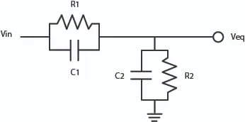
The structure of an RC gain equalizer depends on application requirements. In this example, from optical networking, frequency shaping is achieved using a simple RC network for gain and suppression at the right frequency, which depends on the resistor (R) and capacitor (C) values in the series and parallel networks.

Figure 1. RC equalizer with a simple RC network. Source
Per the example, the transfer function is:

Zero frequency (top) and pole frequency (bottom) are:
%20and%20pole%20frequency%20(bottom)%20(1).webp?width=350&height=269&name=Zero%20frequency%20(top)%20and%20pole%20frequency%20(bottom)%20(1).webp)
Knowles Precision Devices’ DLI brand gain equalizers were designed to and maintain excellent, repeatable performance. For more information on our offerings and component specifications, see our Gain Equalizers product page. For thoughts on implementation, read this piece on gain slope issues in microwave modules.

