

Before jumping into a discussion on ceramic coaxial resonators, it is important to understand what a resonator is and how these electrical components work. In general, a resonator is an essential component for constructing a bandpass filter since the resonator is what will allow specified frequencies, or bands of frequencies, to pass through the filter as shown in Figure 1.
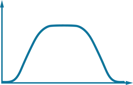
Figure 1. An illustration of how a band pass filter works to pass frequencies between the set upper and lower limits while rejecting all other frequencies.
A simple resonator, such as an LC resonator, can store frequency-dependent electric energy in the capacitance (C) and magnetic energy in the inductance (L). The resonant frequency of a resonator occurs when the energy stored in electric field is equal to the energy stored in the magnetic field.
An Overview of Ceramic Coaxial Resonators
Now that we’ve established the basics of how a resonator works, we can explore how a ceramic coaxial resonator functions. In general, a ceramic coaxial resonator is a transmission line resonator that operates in transverse electromagnetic (TEM) mode. TEM mode has both E- and H-field components at right angles to the z-direction and no signals in the direction of propagation as shown in Figure 2.
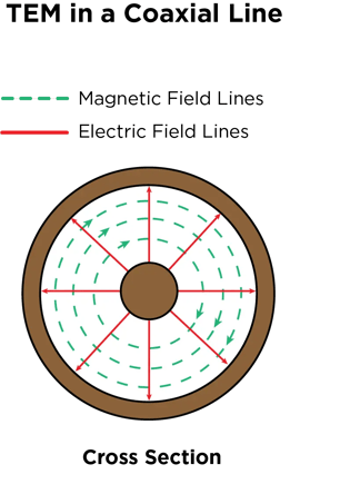
Figure 2. An example showing how electrical and magnetic energy travel in a coaxial transmission line.
A coaxial resonator line is usually configured using a ceramic rectangular prism with a coaxial hole running through the center. The dielectric type, length, and metallization will dictate performance at frequency. The line can also be cut to a specific length related to the wavelength of the frequency of interest. For example, to make the lines shorter we can use ceramics with specific dielectric constants, which will shrink the wavelength of the frequency we are interested in. Figure 3 shows an example of how a signal is impacted when either a λ/4 resonator with one end metallized or a λ/2 resonator with both ends open is added.
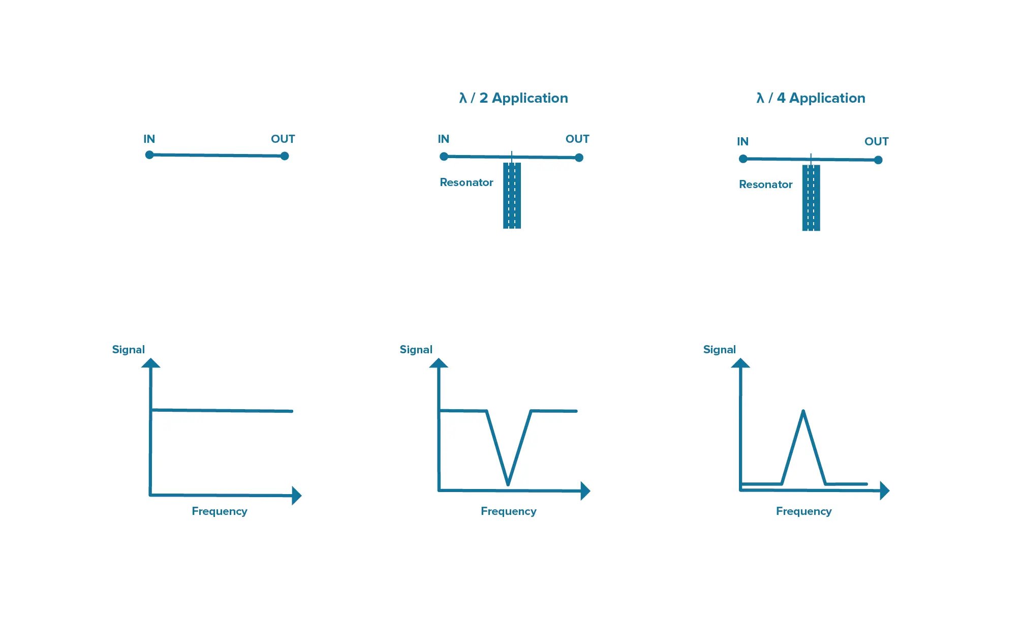
Figure 3. A depiction of how a signal will be impacted depending on the type of ceramic coaxial resonator added.
Using Ceramic Coaxial Resonators to Make Filters
Let’s now look at when it may be advantageous to use ceramic coaxial resonators to create filters. In our blog post, Designing Basic Filter Circuits, we showed a number of examples of how you can construct simple filters from different combinations of resistors (Rs), Cs, and Ls. While this approach is great for developing simple filters, as operating frequencies increase and filtering needs become more complex, you are likely to run into a variety of issues with performance and size if you continue to try to use only these basic circuit building blocks.
Instead, short-circuit ceramic coaxial resonators made with modern high-performance ceramic dielectric materials can be used in place of LC resonators. The high Q possible in the UHF and microwave frequency range makes ceramic coaxial resonators an ideal option for many applications, especially when cost, size, and stability are important.
The Capabilities of Knowles Precision Devices’ Ceramic Coaxial Resonator Filters
At Knowles Precision Devices, we make ceramic coaxial filters in the region highlighted in the plot in Figure 4.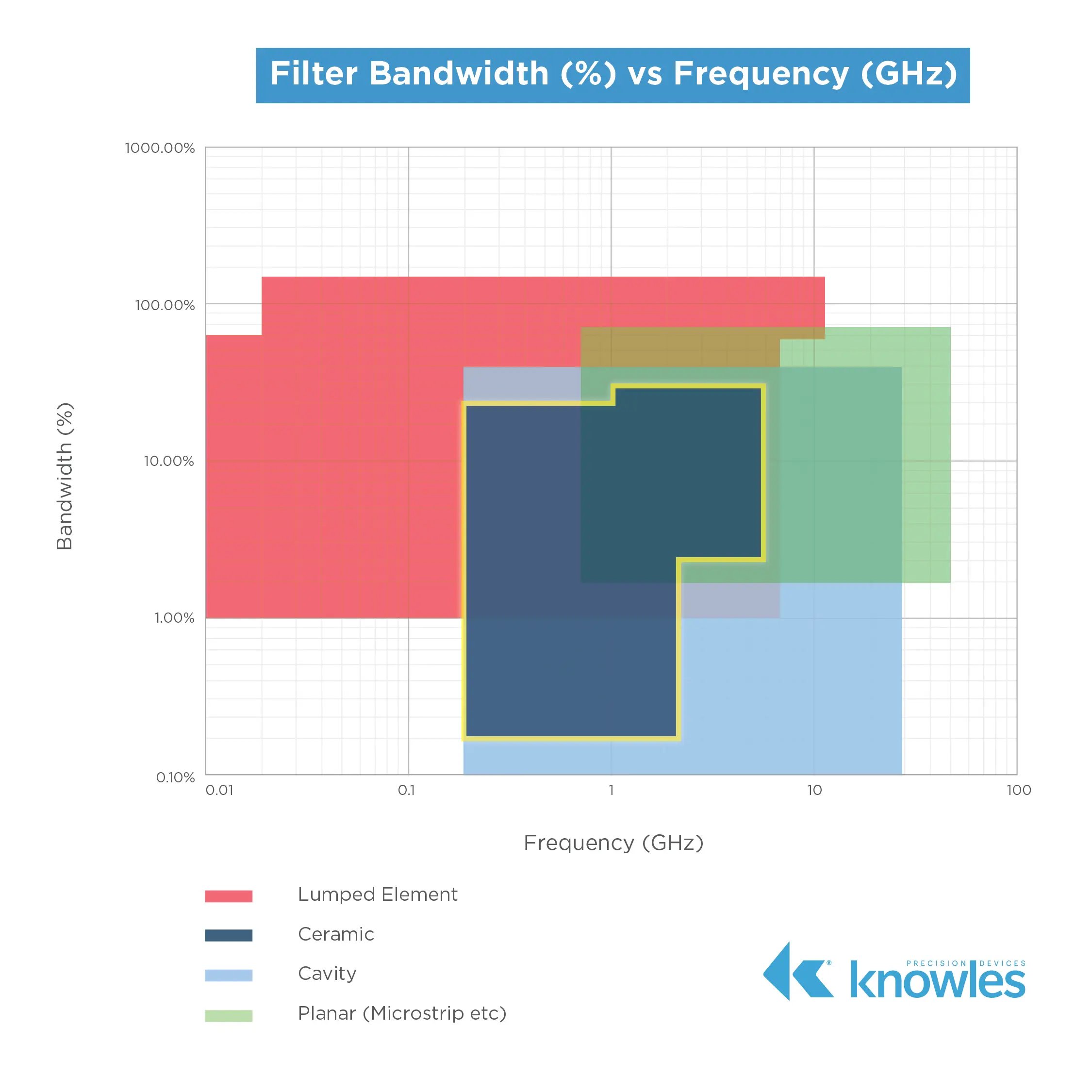
Figure 4. The frequency range covered by our ceramic coaxial resonator filters is shown in the dark blue area highlighted with a yellow outline.
Our customers typically look for ceramic coaxial resonator filters in the following ranges, which we offer:
- Narrow to moderate bandwidths for F0 = 200MHz to 2.2 GHz for large profile 12 mm and 18 mm resonator bandpass filters, 0.2 percent to 30 percent fractional bandwidth.
- Moderate to wide bandwidths for F0 = 1 GHz to 6 GHz for small profile 2 mm to 6 mm resonator bandpass filters, 3 percent to 45 percent fractional bandwidth
- Narrow bandwidth band reject filters for F0 = 400 MHz to 4 GHz, 1 percent to 15 percent fractional bandwidth
View our RF/Microwave Products Catalog to learn more about our custom ceramic filters, resonators, and diplexer options or learn more about some our other common filter types including cavity, lumped element, and microstrip.