
To help customers with filter selection, we generally provide a lot of information on what our filters can do. But in this new Filter Basics Series, we are taking a step back to cover some background information on how filters do what they do. Regardless of the technology behind the filter, there are several key concepts that all filters share that we will dive into throughout this series. By providing this detailed fundamental filter information, we hope to help you simplify your future filtering decisions.
Part 6 expands on part 5 by covering more details on waveguides and transmission lines, including the different types of electromagnetic modes supported by each.
In Part 5, we covered the basics of distributed element filter construction and gave an overview of two important methods for propagating electromagnetic waves around a circuit – waveguides and transmission lines. At a high level, the main difference between these two methods is the number of conductors involved and the types of electromagnetic modes supported. Let’s explore how each of these three types of electromagnetic modes work and how they are supported, or not supported, by waveguides and transmission lines.
Three Types of Electromagnetic Modes
When we say “modes”, what we are referencing is the different solutions to the electromagnetic field equations for the particular structure we are referring to. These three modes include transverse magnetic (TM), transverse electric (TE), and transverse electro-magnetic (TEM).
A TM mode solution involves the electric (E) field having components in the z-direction, which is along the direction of propagation, so that the magnetic (H) field is transverse, or at right angles to the z-direction (Figure 1).
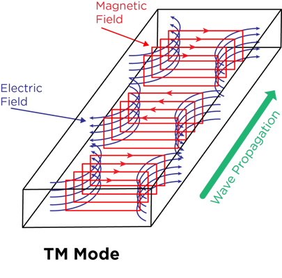
Figure 1. The E and H fields for TM mode moving in a rectangular waveguide.
On the other hand, TE mode has E field components at right angles to the z-direction as shown in Figure 2.

Figure 2. The E and H fields for TE mode moving in a rectangular waveguide.
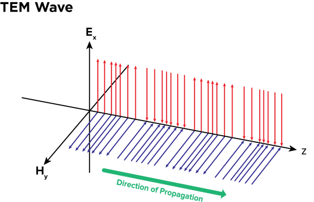
TEM mode has E field and H field components at right angles to the Z direction. Figure 3a shows an example of an electromagnetic wave propagating through space in TEM mode while Figure 3b shows how TEM mode works in a cross-section of a coax cable.
A.
B. 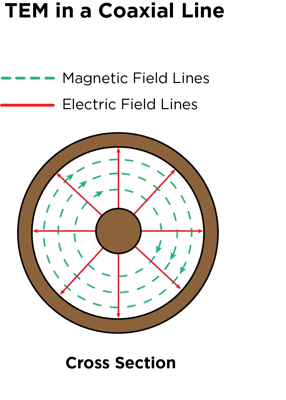
Figures 3a and 3b. These diagrams show examples of how the E and H field move in TEM mode.
The Different Modes Supported by Transmission Lines and Waveguides
When we look at transmission lines and waveguides in terms of the electromagnetic modes supported, we can make clear distinctions between the two. A waveguide is a hollow tube made of a single conducting surface, which means it cannot support TEM mode. We usually see waveguides designed as a metal tube, but in recent years, the development of substrate-integrated waveguide (SIW) technology is changing this. An SIW is basically a rectangular waveguide in which the single conductor walls are formed by plated surfaces and vias. In this format, the wave uses TE mode to propagate in high dielectric-constant materials. A depiction of an SIW is shown in Figure 4.
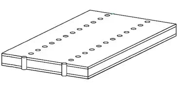
Figure 4. A representation of an SIW.
Since a transmission line is a two-conductor structure, it can carry electromagnetic waves using TEM mode. A common example of a transmission line, although it is sort of going out of style now, is the coax cable shown in Figure 3b, which carries DOCSIS signals to cable TV boxes. Additional transmission line examples, the modes one would usually see, and their traditional performance characteristics compared to what you would see with a waveguide are all outlined in Table 1.
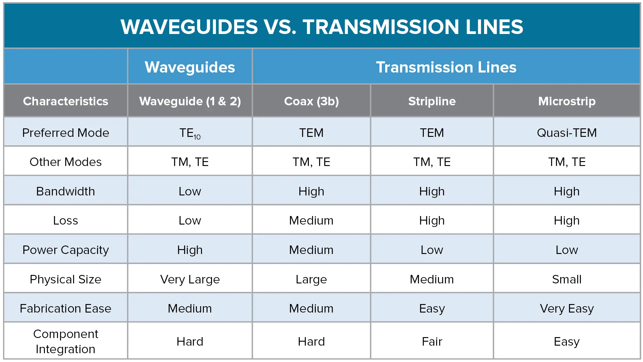
Table 1. With all other qualities of the application being equal, this Table provides an overview of how waveguides and different transmission line methods compare.
To learn how modern approaches to filter design are changing some of these traditional limitations, read part 1 and part 2 of our article published in Microwaves & RF.
To summarize, the biggest thing to remember when it comes to waveguides versus transmission lines is that a waveguide = one conductor (usually a tube) and a transmission line = more than one conductor, such as the structure seen in a coax cable.
In part 7, we will shift gears a bit and cover the different ways you can think about Q factor. In the meantime, read more in this series on our  or take a deeper dive in the fundamentals of RF Filters by downloading the comprehensive Filter Basics guide today.